Cutting insert and replaceable insert-type rotating tool

a technology of rotating tools and cutting inserts, which is applied in the direction of metal-working equipment, metal-working apparatus, milling equipment, etc., can solve the problems of increased production costs, early damage or wear of cutting edges, etc., and achieve the effect of prolonging the service life of tools and reducing production costs

Inactive Publication Date: 2012-11-01
MITSUBISHI MATERIALS CORP
View PDF19 Cites 36 Cited by
  • Summary
  • Abstract
  • Description
  • Claims
  • Application Information

AI Technical Summary

Benefits of technology

[0035]The cutting insert and the replaceable insert-type rotating tool of the present inv...

Problems solved by technology

However, where a face milling cutter is used to cut a work piece made with, for example, a difficult to cut hard material, excessive loads are imparted to the cutting insert due ...

Method used


Image

  • Cutting insert and replaceable insert-type rotating tool
  • Cutting insert and replaceable insert-type rotating tool
  • Cutting insert and replaceable insert-type rotating tool

Examples


Embodiment Construction

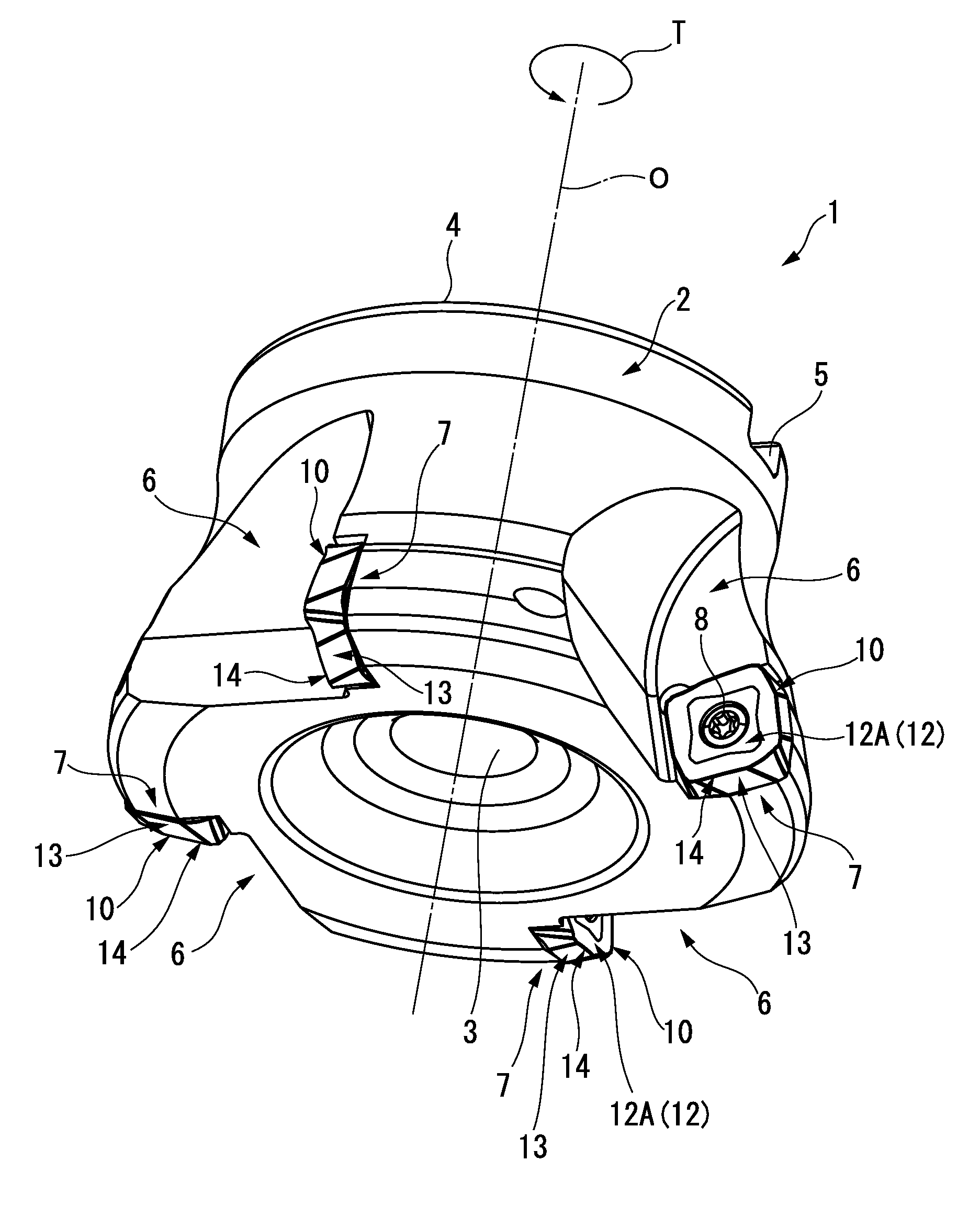
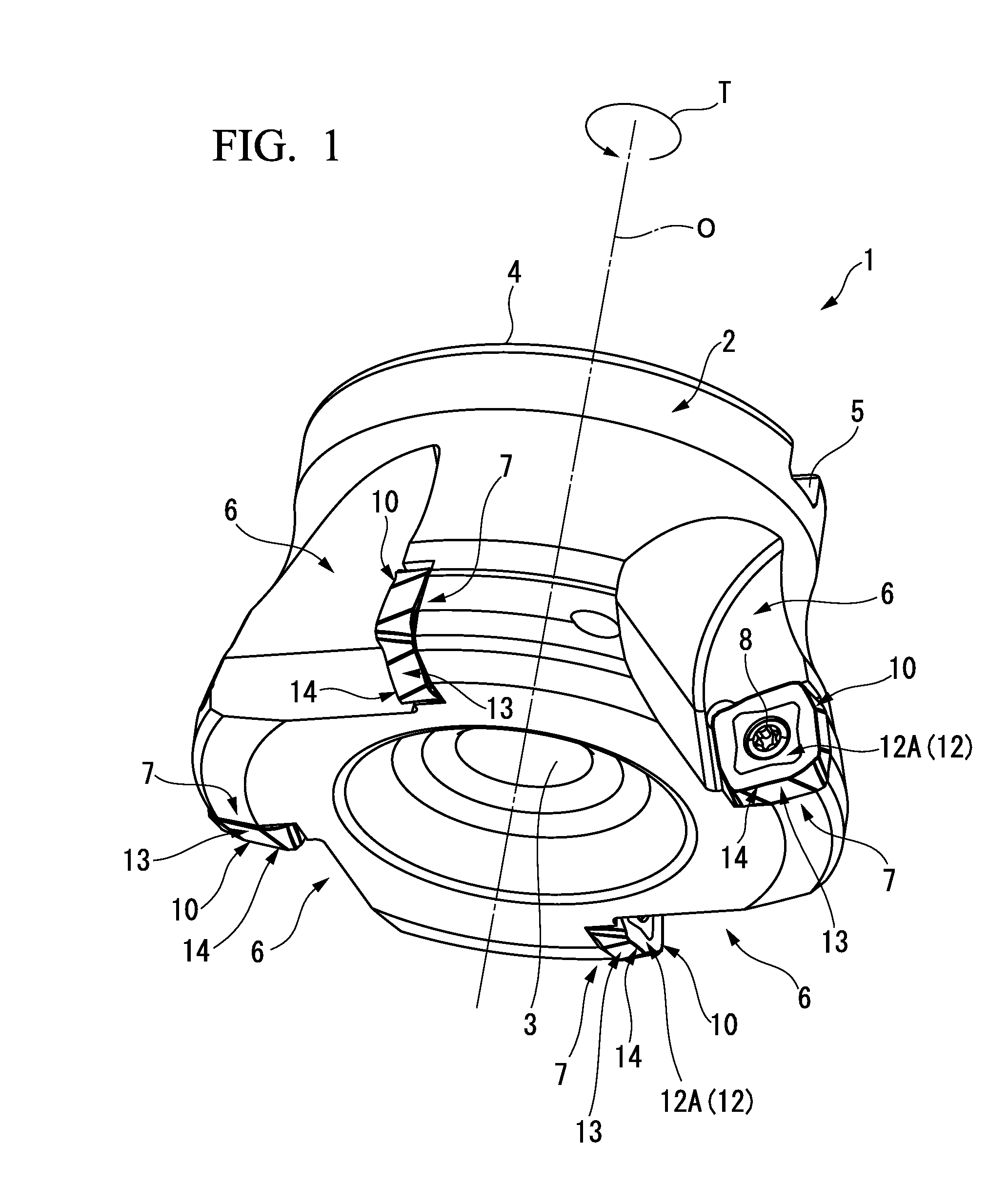
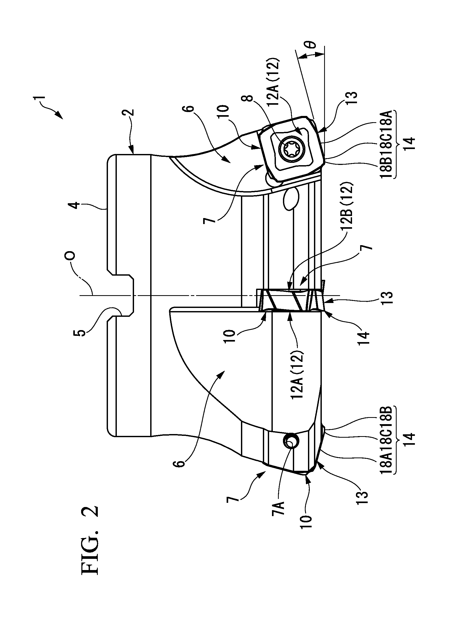
[0046]Each of FIG. 1 to FIG. 3 shows a replaceable insert-type milling cutter 1 which is one embodiment of the replaceable insert-type rotating tool in the present invention. Further, each of FIG. 4 to FIG. 7 shows one embodiment of a cutting insert 10 which is used in the replaceable insert-type milling cutter 1. This replaceable insert-type milling cutter 1 is a replaceable insert-type high speed feeding milling cutter which is used in high speed feeding work. In addition, the cutting insert 10 is a cutting insert for high speed feeding work.

[0047]As shown in FIG. 1 to FIG. 3, in the replaceable insert-type milling cutter 1, a tool main body 2 thereof is formed in a substantially disk-like shape at the center of an axis line O. A tool attaching hole 3 which extends along the axis line O is formed at the center of the tool main body 2 in a radial direction to penetrate through the tool main body 2. A pair of key grooves 5, 5 extending outside in the radial direction from an opening...


PUM

PropertyMeasurementUnit
Angleaaaaaaaaaa
Angleaaaaaaaaaa
Currentaaaaaaaaaa

Abstract

A rake face (12) is formed on the both sides of an insert main body facing outside in the thickness direction thereof to make a pair, a cutting edge (14) is arranged on each side which constitutes an outer periphery of the rake face (12), the cutting edge (14) is provided with a major cutting edge (18A) and a minor cutting edge (18B) A connection part (20) formed in a concave curved shape is formed on the insert main body over the entire thickness direction of the insert main body. Of the pair of rake faces (12), each cutting edge (14) on the outer periphery of the first rake face (12A) and each cutting edge (14) on the outer periphery of the second rake face (12B) have rotation symmetry with each other.

Description

TECHNICAL FIELD[0001]The present invention relates to a cutting insert and a replaceable insert-type rotating tool.[0002]The present application claims the right of priority to Japanese Patent Application No. 2009-236599 filed on Oct. 13, 2009, in Japan, with the content cited herewith.BACKGROUND ART[0003]Conventionally, as a cutting tool for flat working a metal material (work piece), there is known a face milling cutter (replaceable insert-type rotating tool) which is provided with a tool main body having a substantially disk-like shape and rotating around an axis line and a plurality of cutting inserts mounted on an outer circumference of the leading end of the tool main body. The cutting insert is formed, for example, in a tetragonal plate shape and formed with a hard material such as cemented carbide. The cutting insert is mounted detachably on a plurality of insert seats arranged on the outer circumference of the leading end of the tool main body. Further, the cutting insert i...

Claims


Application Information

Patent Timeline
IPC IPC(8): B23C5/06B23C5/20
CPCB23C5/06B23C5/207B23C2200/203Y10T407/23B23C2200/208Y10T407/1924B23C2200/205B23C5/202
Inventor SAITO, TAKAYOSHIDAIGUJI, HISASHI
Owner MITSUBISHI MATERIALS CORP
Why Eureka
Try Eureka