Rfid-based electricity metering system

Inactive Publication Date: 2012-11-08
KIM MOON J
View PDF7 Cites 35 Cited by
  • Summary
  • Abstract
  • Description
  • Claims
  • Application Information

AI Technical Summary

Benefits of technology

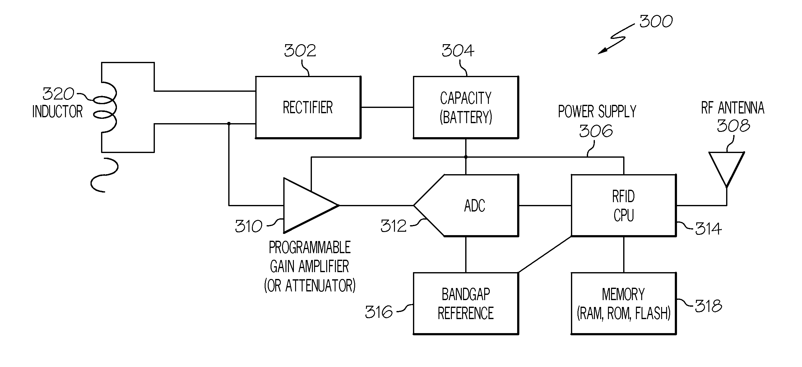
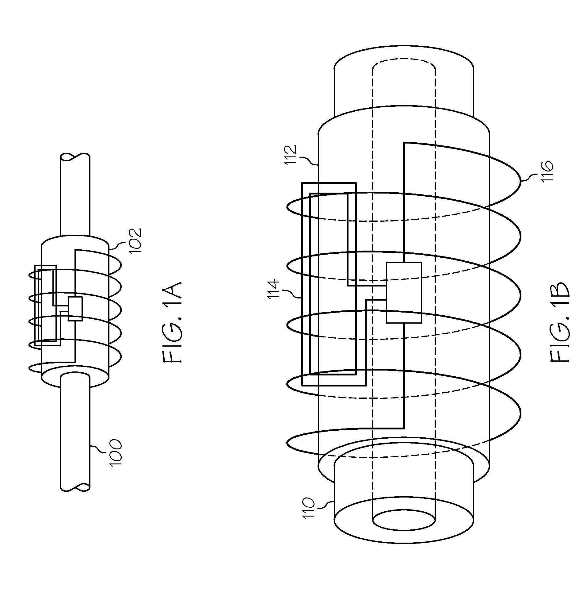
[0012]Embodiments of the present invention provide an RFID-based electricity metering system enabled to meter the energy consumption of individual devices. This is typically accomplished by: producing an induced current through inductive coupling using an inductor affixed to the power line of an electronic device; providing gain or attenuation control on the induced current so that the induced current is properly scaled; converting the amplitude of the induced current to a digital value representing the energy consumption of the electronic device; storing the digital value; and transmitting the digital value within a frequency band to an RFID reader.
[0013]The RFID-based electricity metering system is composed of two main parts: a set (at least one) of RF sensor units and the RFID reader. Two categories of RFID sensor units will be discussed. The first type of RFID, in fact a low frequency ID, sensor unit uses inductive coupling caused from the current flowing through the power line of an electronic device and an affixed power-coupling inductor to supply energy without the need of acquiring power from the RFID reader to perform its functions. The second type is a passive RFID sensor unit in that employs the electromagnetic energy transmitted by the RFID reader as power to perform its functions. Although both types of RFID sensor units are disclosed and discussed, the first type is the primary focus.
[0014]A first aspect of the present invention provides a radio frequency identification (RFID) based electricity metering system for metering the energy consumption of an electronic device, comprising: a set of RFID sensor units, each of the set of RFID sensor units comprising: an inductor affixed to (or embedded in) the power line of an electronic device configured to produce an induced current using the power line of the electronic device through inductive coupling; a programmable gain amplifier (PGA) coupled to the inductor configured to provide gain or attenuation control on the induced current so that the induced current is properly scaled; an analog-to-digital converter (ADC) configured to convert the amplitude of the induced current to a digital value representing the energy consumption of

Problems solved by technology

It is difficult, if not impossible, for the consumer to determine how much energy is being consumed by each device.
More advanced monitoring solutions are costly and typically do not include efficient energy consumption measurement for individual devices.
Heretofore, severa

Method used


Image

  • Rfid-based electricity metering system
  • Rfid-based electricity metering system
  • Rfid-based electricity metering system

Examples


Embodiment Construction

[0025]Exemplary embodiments will now be described more fully hereinafter with reference to the accompanying drawings, in which exemplary embodiments are shown. This disclosure may, however, be embodied in many different forms and should not be construed as limited to the exemplary embodiments set forth therein. Rather, these exemplary embodiments are provided so that this disclosure will be thorough and complete, and will fully convey the scope of this disclosure to those skilled in the art. In the description, details of well-known features and techniques may be omitted to avoid unnecessarily obscuring the presented embodiments.

[0026]The terminology used herein is for the purpose of describing particular embodiments only and is not intended to be limiting of this disclosure. As used herein, the singular forms “a”, “an”, and “the” are intended to include the plural forms as well, unless the context clearly indicates otherwise. Furthermore, the use of the terms “a”, “an”, etc., do no...


PUM


Abstract

Embodiments of the present invention provide a radio frequency identification (RFID) based electricity metering system enabled to meter energy consumption of individual devices. Specifically, embodiments of this invention provide a set (a least one) of RFID sensor units, each RFID sensor unit comprising: an inductor affixed to the power line of an electronic device configured to produce an induced current using the power line of the electronic device through inductive coupling; a programmable gain amplifier (PGA) coupled to the inductor configured to provide gain or attenuation control on the induced current so that the induced current is properly scaled; an analog-to-digital converter (ADC) configured to convert the amplitude of the induced current to a digital value representing the energy consumption of the electronic device; a central processing unit (CPU) coupled to the ADC configured to receive the digital value from the ADC; a memory unit configured to store the digital value from the CPU; an antenna coupled to the CPU configured to transmit the digital value within a frequency band; and an RFID reader configured to receive the digital value transmitted by the RFID sensor unit.

Description

FIELD OF THE INVENTION[0001]The present invention relates to energy metering systems. In particular, the present invention is directed to a system for an RFID-based electricity metering system enabled to meter energy consumption of individual devices.BACKGROUND OF THE INVENTION[0002]An electricity meter is an electronic device that measures the amount of electric energy consumed by a residence, business, or an electrically powered device. As commercial use of electric energy spread in the late nineteenth century, the use of the electric energy meter became important in order to properly bill customers for the cost of energy. Electricity meters are typically calibrated in billing units, the most common one being the kilowatt hour. Periodic readings of electricity meters establish billing cycles and energy used during a cycle.[0003]Conventional electricity meters invasively measure too sparingly (once a month) and feedback to the consumer (via a bill for energy consumed) can take stil...

Claims


Application Information

Patent Timeline
IPC IPC(8): G08C15/06
CPCH04Q9/00H04Q2209/47
Inventor KIM, MOON J.
Owner KIM MOON J
Why Eureka
Try Eureka