Pneumatic tire

Active Publication Date: 2012-11-15
YOKOHAMA RUBBER CO LTD
View PDF10 Cites 35 Cited by
  • Summary
  • Abstract
  • Description
  • Claims
  • Application Information

AI Technical Summary

Benefits of technology

[0011]A pneumatic tire according the aspect explained heretofore can improve both a steering stab

Problems solved by technology

However, with such a tread pattern, it is difficult to maintain the steering stability performance of the vehicle on dry roads because a mechanical rigidity (tread rigidity) of a land section formed in the tread section declines.
Due to the higher performance

Method used


Image

  • Pneumatic tire
  • Pneumatic tire
  • Pneumatic tire

Examples


Example

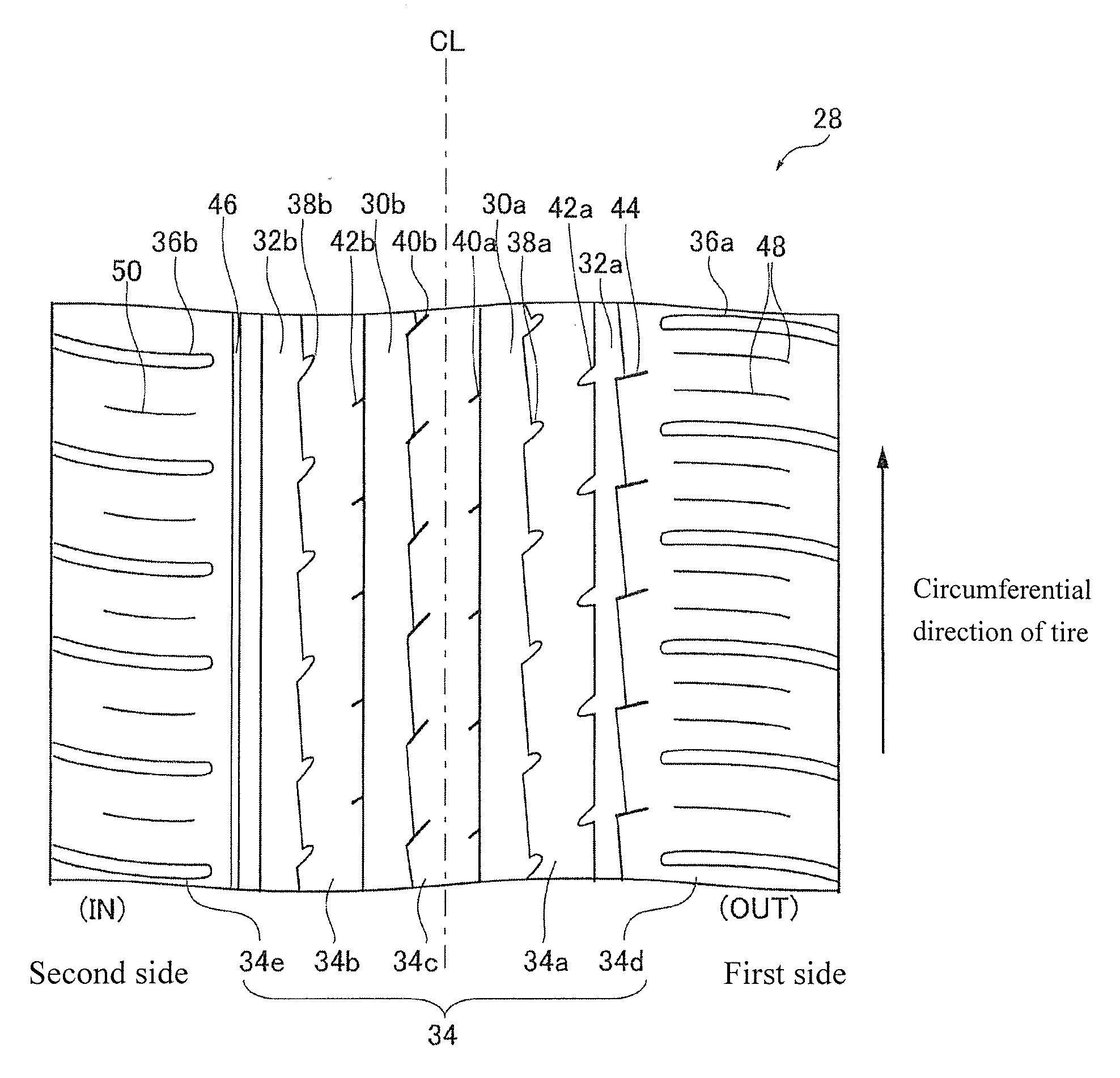
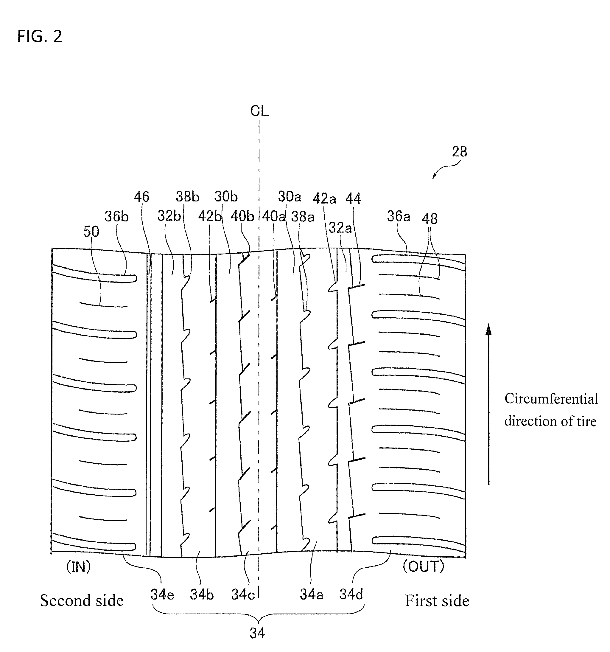
[0054]Comparing the results for the working example 1 and the comparative examples 1 to 3 shown in Table 1 demonstrates that positioning the terminal ends of the shoulder lug grooves 36a and 36b in positions separated from the outside main groove 32a and the inside main groove 32b, respectively, i.e., closing the shoulder lug grooves 36a and 36b such that they do not communicate with the outside main groove 32a and 32b, enables both the dry steering stability performance and the wet steering stability performance to be improved. Meanwhile, as show in the working examples 2 to 5, the dry steering stability performance and the wet steering stability performance are both improved even if the end positions of the shoulder lug grooves 36a and 36b are varied.

[0055]Further working examples 6 to 14 of tread patterns were also fabricated and evaluated with respect to the performance characteristics explained above. The working examples 6 to 10 are variations of the tread pattern shown in FIG...

Example

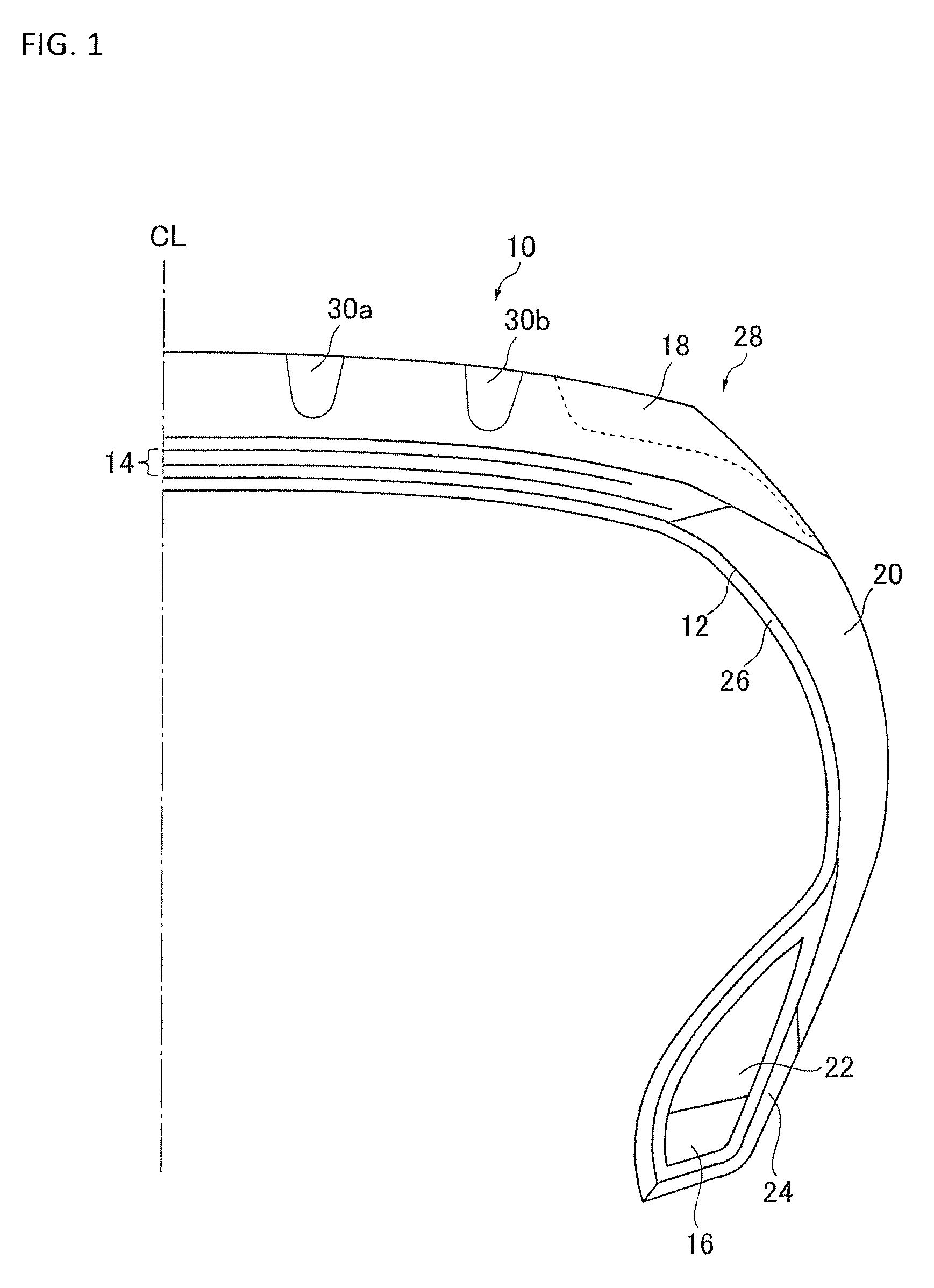
[0058]As shown in Table 3, similarly to the working example 1, the working examples 15 to 20 can improve both the dry steering stability performance and the wet steering stability performance. Thus, in this embodiment, the tire-widthwise centers of the center main grooves 30a and 30b are separated from the tire centerline CL by a distance equal to at least 8% and not larger than 12% of the ground contact width and the tire-widthwise centers of the outside main groove 32a and the inside main groove 32b are separated from the tire centerline CL by a distance equal to at least 26% and not larger than 32% of the ground contact width. Additionally, assuming Wmax is a maximum groove width among the center main grooves 30a and 30b and the inside main groove 32b and assuming Wout is a groove width of the outside main groove 32a, the ratio Wmax / Wout is at least 1.5 and not larger than 2.5. The groove area ratio Sin of the region of the ground contact surface located on the second side of the...


PUM


Abstract

A pneumatic tire for improving steering stability performance on dry and wet road surfaces. The tire tread pattern has circumferential center main grooves, outside and inside main grooves, land sections demarcated by the main grooves, ground contact borders on both sides of the tire, and closed shoulder lug grooves. A ratio Wmax/Wout of a maximum main groove width Wmax and an outside main groove width Wout is at between 1.5 and 2.5 inclusive. A ratio Sin/Sout of a groove area ratio Sin of a region on a tire-widthwise second side of a tire centerline and a groove area ratio Sout of a region on a first side of the tire centerline is at least 1.10 and smaller than 1.25. A groove area ratio of a region on the second side of a tire-widthwise centerline of the intermediate land sections exceeds that of a region on the first side.

Description

CROSS-REFERENCE TO RELATED APPLICATIONS[0001]This application claims priority to Japanese Patent Application No. 2011-105373, filed on May 10, 2011, the entire disclosure of which is hereby incorporated herein by reference.BACKGROUND[0002]1. Field of the Invention[0003]The present invention relates to a pneumatic tire. More particularly, the present invention relates to a pneumatic tire having improved steering stability performance on both dry and wet road surfaces.[0004]2. Background Information[0005]With the higher performance levels of vehicles in recent years, there is a stronger demand for a pneumatic tire that can provide stable steering performance on wet road surfaces and stable steering performance on dry road surfaces during high speed travel. In order to improve the steering stability performance of a vehicle on wet road surfaces, pneumatic tires are generally provided with a tread pattern that has many lug grooves and sipes in a tread section to evacuate water efficient...

Claims


Application Information

Patent Timeline
IPC IPC(8): B60C11/117
CPCB60C11/1392B60C11/0304B60C11/12B60C2011/0353B60C2011/0381B60C11/033Y10S152/03B60C2011/0348B60C2011/0393
Inventor KAMEDA, NORIFUMI
Owner YOKOHAMA RUBBER CO LTD
Why Eureka
Try Eureka