

Fuel cell
- Summary
- Abstract
- Description
- Claims
- Application Information
AI Technical Summary
Benefits of technology
Problems solved by technology
Method used
Image

Examples
first embodiment
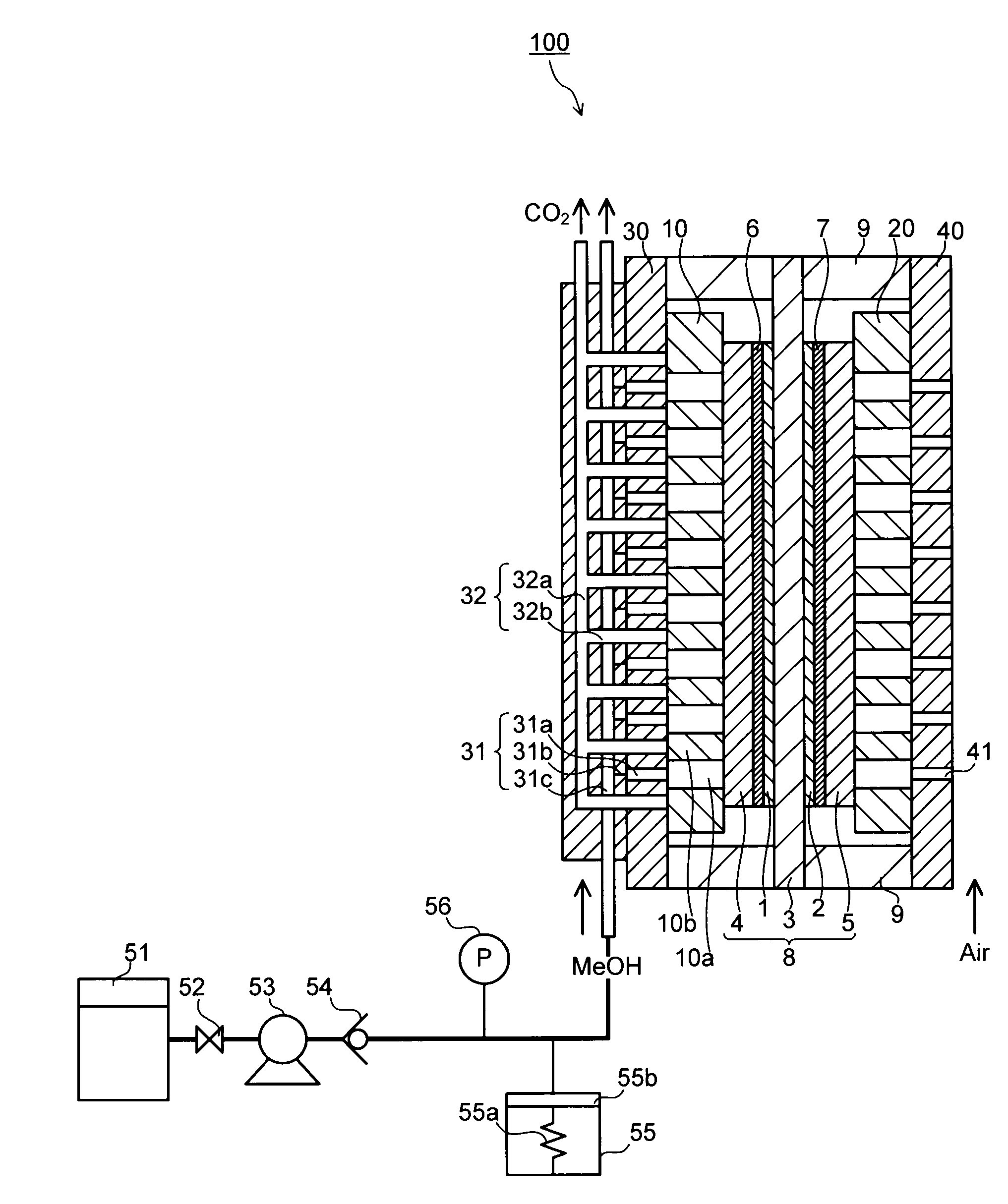
[0019]FIG. 1 is a cross sectional view schematically showing the structure of a fuel cell according to a first embodiment. In FIG. 1, the fuel cell 100 includes a membrane electrode assembly (MEA) 8 containing an electrolyte membrane 3, an anode (anode catalytic layer 1 and an anode gas diffusion layer 4) and a cathode (cathode catalytic layer 2 and a cathode gas diffusion layer 5) which are opposite to one another via the electrolyte membrane 3, a hydrophobic porous body 10, an anode channel body 30 adjacent to the hydrophobic porous structure 10, and a cathode channel body 40 which is disposed opposite to the anode channel body 30 via the membrane electrode assembly 8.
[0020]The membrane electrode assembly 8 includes the electrolytic membrane 3 made of proton conductive solid polymer membrane, the anode catalytic layer 1 and the cathode catalytic layer 2 which are formed by applying catalytic layers on the main surface of the electrolytic membrane 3, the anode diffusion layer 4 and...
second embodiment
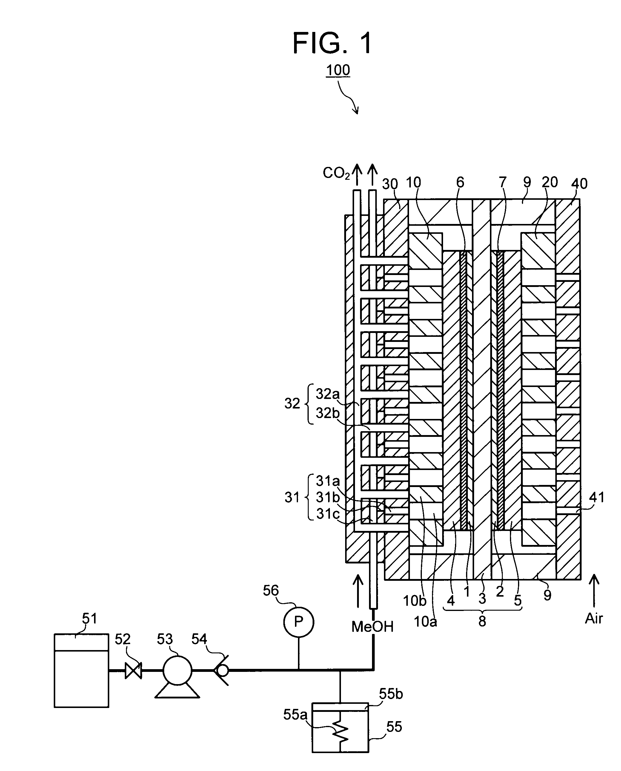
[0040]FIG. 2 is a cross sectional view schematically showing the structure of a fuel cell according to a second embodiment. In FIGS. 1 and 2, like or corresponding constituent components are designated by the same reference numerals.
[0041]As apparent from FIG. 2, the second embodiment is an embodiment modified from the first embodiment so that the fuel cell in this embodiment is configured similar to the one in the first embodiment except that the check valve 54 in FIG. 1 is substituted with a valve 57. In this embodiment, therefore, explanation is centered on the different structure between the first embodiment and the second embodiment so that explanation for like or corresponding constituent components will be omitted.
[0042]In this embodiment, the supply of the fuel to the anode will be conducted in the same manner as the first embodiment. Concretely, in the third paths 31c, the fuel is temporarily supplied to the pressurized fuel supplier 55 from the fuel tank 51 via the valve 5...
third embodiment
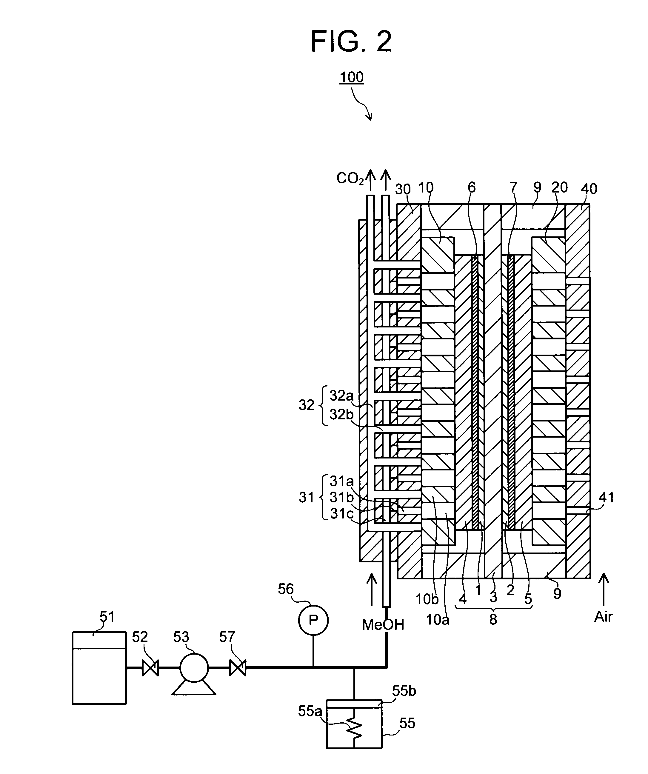
[0046]FIG. 3 is a cross sectional view schematically showing the structure of a fuel cell according to a third embodiment. In FIGS. 1 and 3, like or corresponding constituent components are designated by the same reference numerals.
[0047]As apparent from FIG. 3, the third embodiment is an embodiment modified from the first embodiment so that the fuel cell in this embodiment is configured similar to the one in the first embodiment except that a pressurizing mechanism 58 is provided in the fuel tank 51. According to the pressurizing mechanism 58, the pressure of the fuel reserved in the fuel tank 51 is set higher than the pressure of the fuel reserved in the pressurized fuel supplier 55. In this embodiment, therefore, explanation is centered on the different structure between the first embodiment and the third embodiment so that explanation for like or corresponding constituent components will be omitted.
[0048]In this embodiment, the supply of the fuel to the anode will be conducted i...
PUM
 Abstract
Description
Claims
Application Information