Vehicle passenger detection system

a passenger detection and passenger technology, applied in the direction of vehicular safety arrangements, pedestrian/occupant safety arrangements, instruments, etc., can solve the problems of seating determination accuracy decline, seating determination accuracy drop, and the detection signal from the load sensor is severely influenced, so as to reduce the likelihood, reduce the chance of executing a determination, and reduce the deferral of seating determination

Active Publication Date: 2012-11-15
CALSONIC KANSEI CORP
View PDF18 Cites 6 Cited by
  • Summary
  • Abstract
  • Description
  • Claims
  • Application Information

AI Technical Summary

Benefits of technology

[0010]With this aspect of the present invention, the vibration threshold value setting section sets the vibration threshold value to a higher value when a fluctuation amount of the load detection signal is small than when the fluctuation amount of the load detection signal is large. Thus, setting the vibration threshold value higher serves to decrease the likelihood that the vibration determining section (which determines whether or not a vehicle vibration is occurring) will determine that a vehicle vibration has occurred. In other words, when the fluctuation amount of the load detection signal is small, the vibration determining section is more likely to determine that the vehicle vibration is not occurring than when the fluctuation amount of the load detection signal is large.
[0011]As a result, fo

Problems solved by technology

However, when the vehicle is moving or in another state in which a vehicle vibration occurs, a detection signal from the load sensor varies severely and there is a possibility a seating determination will be incorrect.
When a seating determination is executed or deferred depending on the size of a vehicle vibration, there are situations in which the precision of the seating determination may decline.
For example, if a passenger boards the vehicle while it is stopped and does not sit fully and stably in the seat until after the

Method used


Image

  • Vehicle passenger detection system
  • Vehicle passenger detection system
  • Vehicle passenger detection system

Examples


Embodiment Construction

[0021]Selected embodiments will now be explained with reference to the drawings. It will be apparent to those skilled in the art from this disclosure that the following descriptions of the embodiments are provided for illustration only and not for the purpose of limiting the invention as defined by the appended claims and their equivalents.

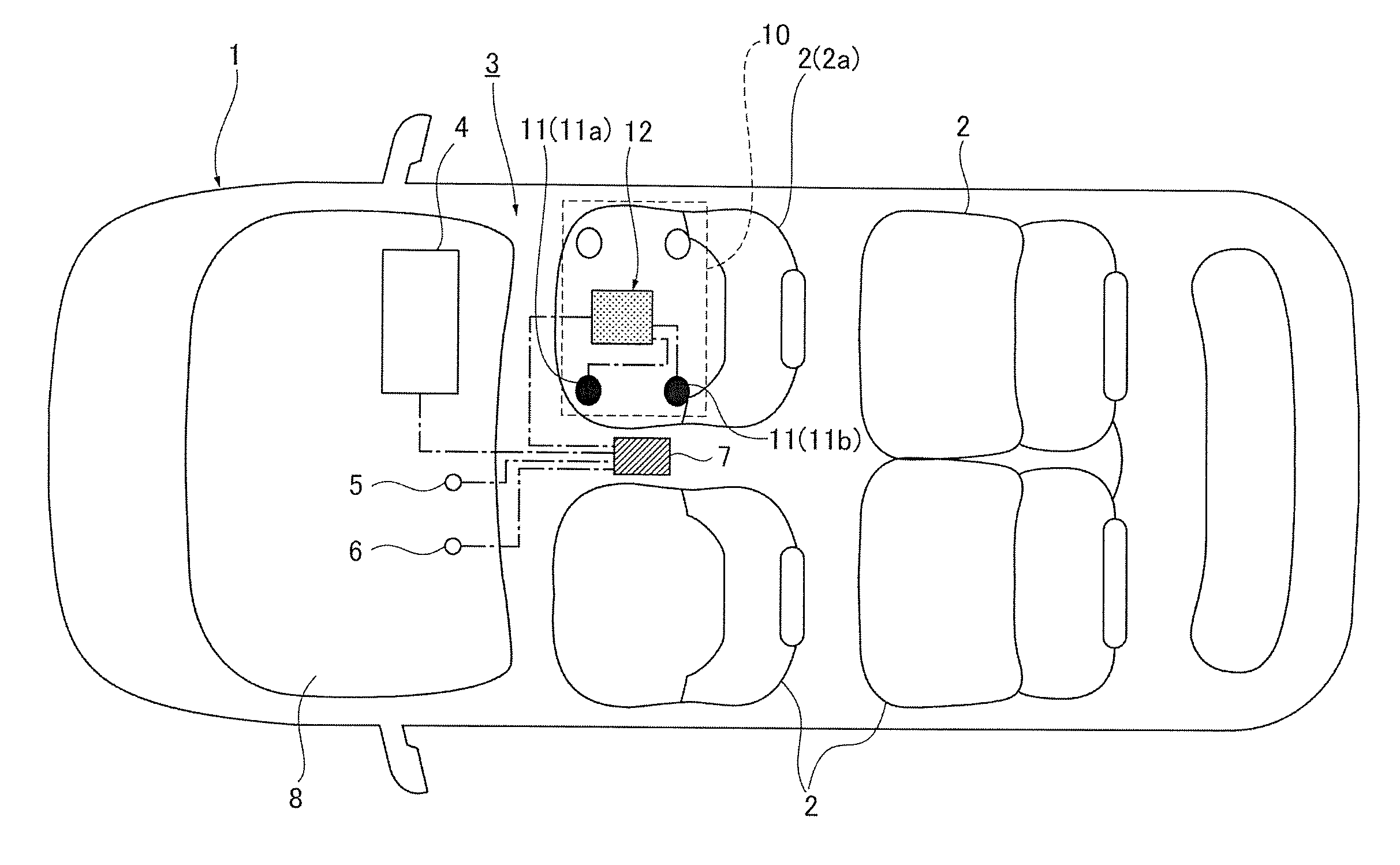
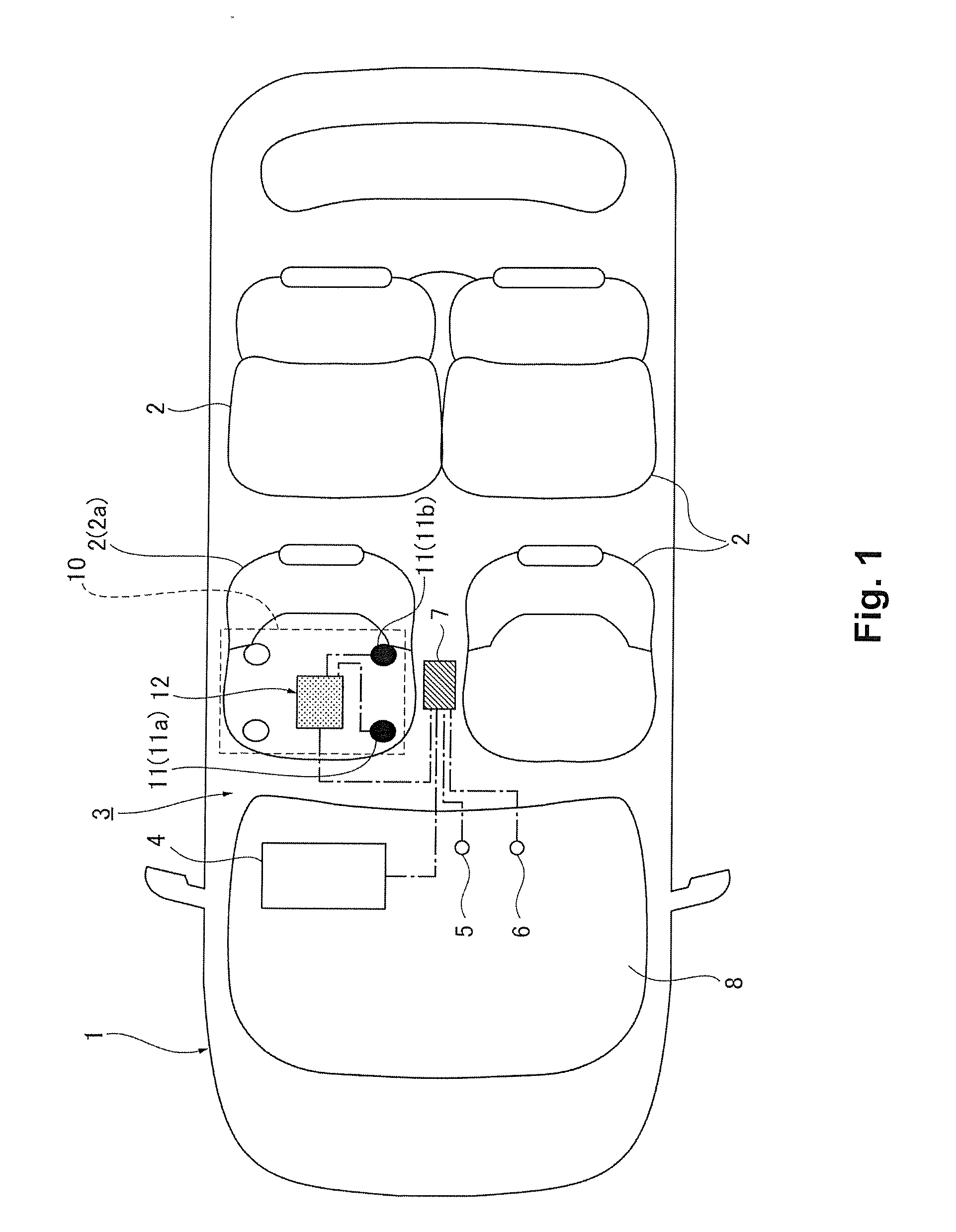
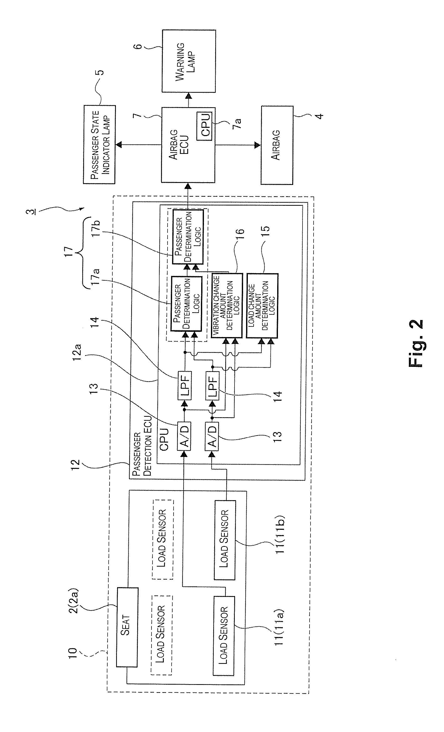
[0022]FIG. 1 is schematic plan view of a vehicle equipped with a vehicle passenger detection apparatus according to one embodiment. FIG. 2 is a block diagram of an air bag system having a vehicle passenger detection apparatus according to the embodiment.

[0023]As shown in FIG. 1, a plurality of seats 2 for passengers to sit on and an air bag system 3 that can protect a passenger seated on a seat 2 are installed in a vehicle 1 (automobile or the like). As shown in FIG. 2, the air bag system 3 comprises an air bag 4, a passenger condition indicator lamp 5, a warning lamp 6, an air bag ECU 7, and a vehicle passenger detection apparatus 10.

[0024]The ai...


PUM


Abstract

A vehicle passenger detection apparatus includes a load detecting part and a seat condition determining part. The seat condition determining part includes a vibration threshold value setting section, a vibration determining section and a seat determining section. The vibration threshold value setting section sets a vibration threshold value based on the load detection signal such that the vibration threshold value is higher when a fluctuation amount of the load detection signal is small than when the fluctuation amount of the load detection signal is large. The seat determining section executes a seating determination based on the load detection signal when the vibration determining section determines that the vehicle vibration is not occurring based on the load detection signal and the vibration threshold value, and to defer execution of the seating determination to maintain a previous seating determination result when the vibration determining section determines that the vehicle vibration is occurring.

Description

CROSS-REFERENCE TO RELATED APPLICATIONS[0001]This application claims priority to Japanese Patent Application No. 2011-108331 filed on May 13, 2011. The entire disclosure of Japanese Patent Application No. 2011-108331 is hereby incorporated herein by reference.BACKGROUND[0002]1. Technical Field[0003]The present invention relates to a vehicle passenger detection apparatus that is installed in an automobile or other vehicle and used to determine whether or not to activate an air bag device provided in the vehicle.[0004]2. Related Art[0005]Air bag systems that can protect a passenger seated in a seat have been provided in automobiles and other vehicles for some time. Such an air bag system has a vehicle passenger detection apparatus that determines if a passenger is seated in a seat or not and if a seated passenger is an adult or a child. The vehicle passenger detection apparatus has a load sensor installed on a set periphery and a seat condition determining part that executes a seating...

Claims


Application Information

Patent Timeline
IPC IPC(8): G01G19/08B60N2/90
CPCB60N2/002G01G19/4142G01G23/01G01G3/1414B60R21/01516
Inventor SORIMACHI, MUTSUMI
Owner CALSONIC KANSEI CORP
Why Eureka
Try Eureka