Light alloy wheel

Inactive Publication Date: 2012-11-15
WASHI KOSAN
View PDF5 Cites 8 Cited by
  • Summary
  • Abstract
  • Description
  • Claims
  • Application Information

AI Technical Summary

Benefits of technology

[0028]According to the light alloy wheel of the present invention, since the inner circumferential flange is provided in addition to the outer circumferential flange, the longitudinal rigidity is improved, and furthermore, since a circumferential edge of the outer circumferential flange is bent in the axial direction of the light alloy wheel, the lateral rigidity is improved.
[0029]Therefore, the light alloy wheel has excellent longitudinal and lateral rigidities.
[0030]Here, generally, the thickness and the length of the outer circumferential flange are determined according to the size of a vehicle to which the light alloy wheels are attached.
[0031]According to the light alloy wheel of the present invention, since the length of the inner circumferential flange is made shorter than the length of the outer circumferential flange, the light alloy wheel can be reliably prevented from hitting a suspension, and in addition, since the average thickness of the inner circumferential flange is made thicker than the average thickness of the outer circumferential flange, the strength of the inner circumferential flange can be improved, and therefore the rigidity of the whole light alloy wheel itself can also be improved.
[0032]According to the light alloy wheel of the present invention, in the case where the inner circumferential flange is so provided as to be perpendicular to the axis of the light alloy wheel, the longitudinal rigidity is reliably improved.
[0033]According to the light alloy wheel of the present invention, in the case where the circumferential edge of the inner circumferential flange is further axially bent, the lateral rigidity is further improved.

Problems solved by technology

The increase in wheel size, however, has the disadvantage of easily deflecting a substantially-cylindrical inner rim.

Method used


Image

  • Light alloy wheel
  • Light alloy wheel
  • Light alloy wheel

Examples


first embodiment

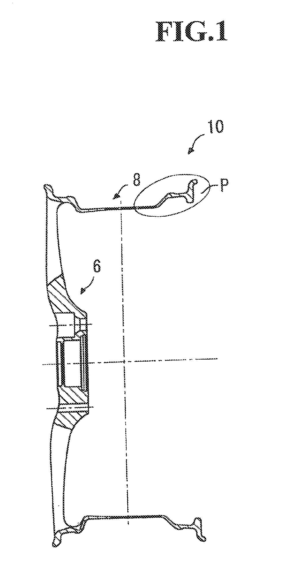
[0058]FIG. 1 is a sectional view showing a light alloy wheel according to a first embodiment.

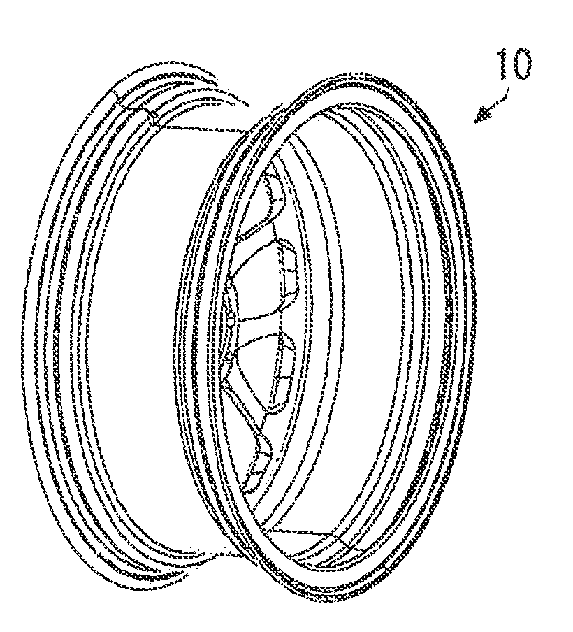
[0059]As shown in FIG. 1, a light alloy wheel 10 according to the first embodiment is provided with a disk portion 6, an inner rim portion 8 elected along a circumferential edge of the disk portion 6, and an outer rim portion erected along a circumferential edge of the disk portion 6.

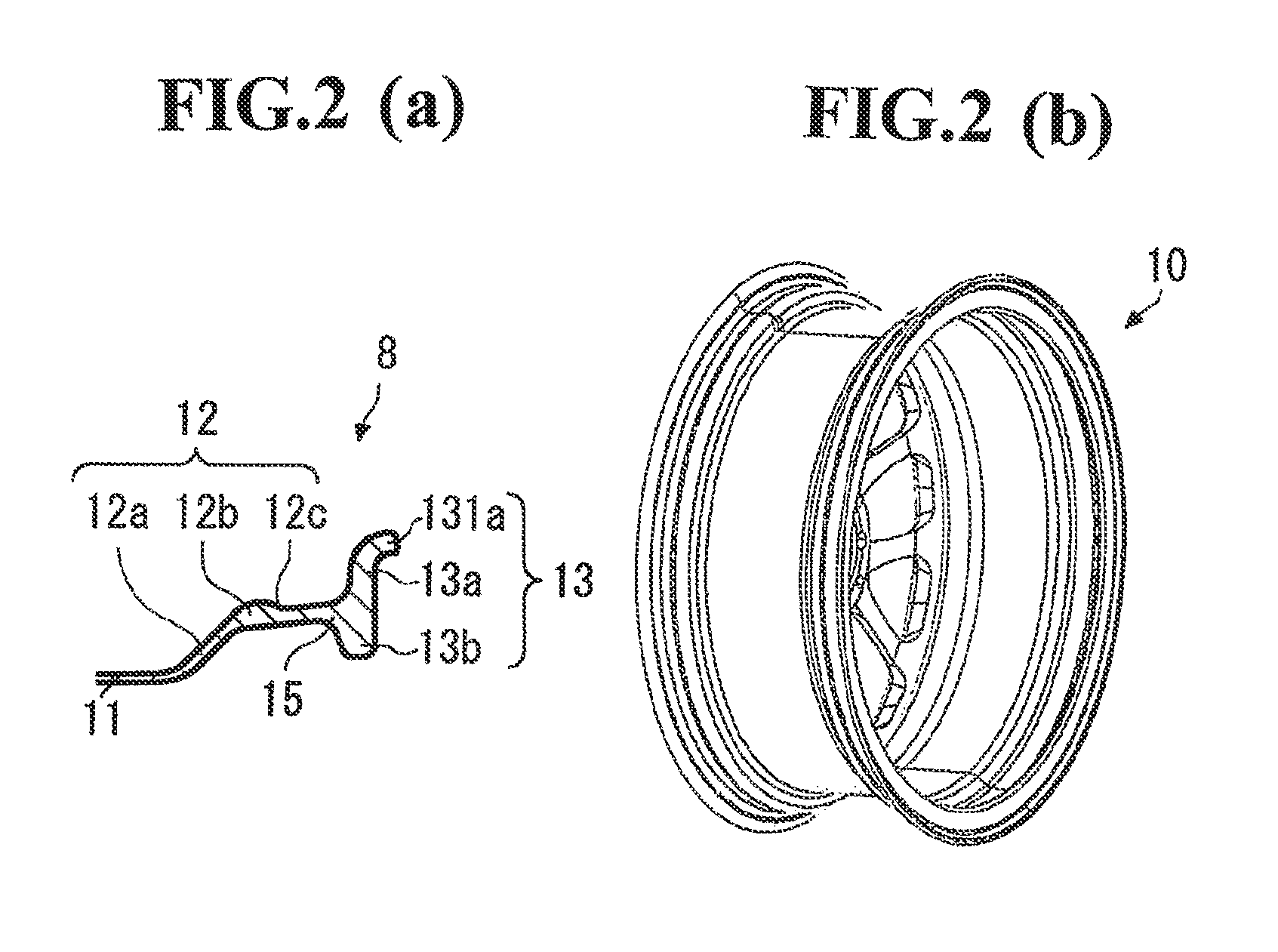
[0060]FIG. 2A is an enlarged sectional view showing a portion P in FIG. 1, and FIG. 2B is a perspective view showing the light alloy wheel according to the first embodiment.

[0061]As shown in FIGS. 2A and 2B, in the light alloy wheel 10 according to the first embodiment, the inner rim portion 8 is provided with a well portion 11 vertically erected along the circumferential edge of the disk portion 6, a rim middle portion 12 continuous with the well portion 11, and an inner rim flange portion 13 connected with a junction portion 15 at a distal end of the rim middle portion 12.

[0062]The rim middle portion 12 is com...

second embodiment

[0078]A light alloy wheel according to a second embodiment is the same as the light alloy wheel 10 according to the first embodiment, except that the shapes of both the inner rim flange portions are different from each other.

[0079]FIG. 3A is an enlarged sectional view showing the inner rim portion of the light alloy wheel according to the second embodiment, and FIG. 3B is a perspective view showing the light alloy wheel according to the second embodiment.

[0080]As shown in FIGS. 3A and 3B, in a light alloy wheel 20 according to the second embodiment, an inner rim portion 18 is provided with a well portion 21 vertically erected along a circumferential edge of a disk portion, a rim middle portion 22 continuous with the well portion 21, and an inner rim flange portion 23 connected with a junction portion 25 at a distal end of the rim middle portion 22.

[0081]The inner rim flange portion 23 has an outer circumferential flange 23a extending outward from the junction portion 25, an outer ci...

third embodiment

[0084]A light alloy wheel according to a third embodiment has a structure where the light alloy wheel 10 according to the first embodiment is provided with well ribs.

[0085]FIG. 4A is an enlarged sectional view showing an inner rim portion of the light alloy wheel according to the third embodiment, and FIG. 4B is a perspective view showing the light alloy wheel according to the third embodiment.

[0086]As shown in FIGS. 4A and 4B, in the right allot wheel 30 according to the third embodiment, the inner rim portion 8 has the well portion 11 provided with well ribs 80.

[0087]The well rib 80 is connected to the connection portion 12a and an outer rim portion 34.

[0088]In the light alloy wheel 30 according to the third embodiment, since the well ribs 80 are provided, the longitudinal rigidity of the well portion 11 is further improved, and a strain due to a difference between a torque on the disk portion side in the axial direction and a torque on the inner rim flange side in the same direct...


PUM


Abstract

A light alloy wheel having excellent longitudinal and lateral rigidities is provided.The present invention is a light alloy wheel 10 for a vehicle provided with a disk portion 6 and an inner rim portion 8 erected along a circumferential edge of the disk portion 6, wherein the inner rim portion 8 includes a well portion 11 erected vertically along the circumferential edge of the disk portion 6, a rim middle portion 12 continuous with the well portion 11, and an inner rim flange portion 13 connected to a junction portion 15 at a distal end of the rim middle portion 12, the inner rim flange portion 13 includes an outer circumferential flange 13a extending outward from the junction portion 15, and an inner circumferential flange 13b extending inward from the junction portion 15, and a circumferential edge of the outer circumferential flange 13a is bent in an axial direction of the light alloy wheel.

Description

TECHNICAL FIELD [0001]The present invention relates to a light weight wheel whose rigidity is improved by reinforcing a rim.BACKGROUND ART [0002]Generally, a vehicle running on a road wears tyres, and is equipped with metal wheels supporting the tyres.[0003]In recent years, such a wheel has been desired to be as light as possible and to have an excellent design. In addition, particularly in passenger automobiles, the size of a wheel is on the increase in order to reduce vibrations and to improve steering performance during running.[0004]The increase in wheel size, however, has the disadvantage of easily deflecting a substantially-cylindrical inner rim.[0005]Regarding this, methods of reinforcing an inner rim flange of the inner rim have been discussed.[0006]For example, an automotive wheel made of a composite material, where a rim has a bead holding flange, and the bead holding flange is provided with a U-shaped cavity extending along the entire circumference of the rim, is known (f...

Claims


Application Information

Patent Timeline
IPC IPC(8): B60B21/00
CPCB60B1/06B60B21/026B60Y2200/11B60B2360/104B60B2900/111B60B21/106Y02T10/86
Inventor ONO, KOTARO
Owner WASHI KOSAN
Why Eureka
Try Eureka