Control device having a night light

a control device and night light technology, applied in the direction of emergency actuators, electric circuit arrangements, legends, etc., can solve the problems of limited lifetime, low efficiency, flickering of lighting loads, etc., and achieve the effect of easy finding and good off-angle viewing

Inactive Publication Date: 2012-11-15
LUTRON TECH CO LLC
View PDF8 Cites 175 Cited by
  • Summary
  • Abstract
  • Description
  • Claims
  • Application Information

AI Technical Summary

Benefits of technology

[0008]The present invention provides a night light for a control device that allows the control device to be easily found when the control device is located in a dark space. The night light is illuminated by a low-power night light circuit, such that the night light may be provided in a battery-powered remote control that has an acceptable battery lifetime (e.g., approximately three years). The night light comprises a lens that conducts the light from the night light circuit to the surface of the remote control and provides good off-angle viewing of the night light. In addition, the night light may be provided on a button of the remote control, for example, a button that causes a lighting load to be illuminated upon actuation. The lens of the night light may be raised from the surface of the button to provide tactile feedback to assist a user in locating the button that causes the lighting load to be illuminated when the control device is being operated in the dark space.

Problems solved by technology

In addition, some prior art dimmer switches dimly backlit one or more of the actuators when the controlled lighting load was off.
However, if the dimmer switch is a “two-wire” device without a connection to the neutral side of the AC power source, the current required to illuminate the night light often needs to be conducted through the lighting load.
When the magnitude of the current conducted through the lighting loads is too great, the lighting loads may flicker or provide otherwise poor performance.
However, some of the wireless remote controls of the prior art lighting control systems were powered by batteries, which have limited lifetimes that are dependent upon the usage and the total current drawn from the batteries as well as how often the remote controls are used.
The prior art battery-powered remote controls did not provide night lights, and simply illuminated the visual indicators for a period of time after one of the buttons of the remote control was actuated.

Method used


Image

  • Control device having a night light
  • Control device having a night light
  • Control device having a night light

Examples


first embodiment

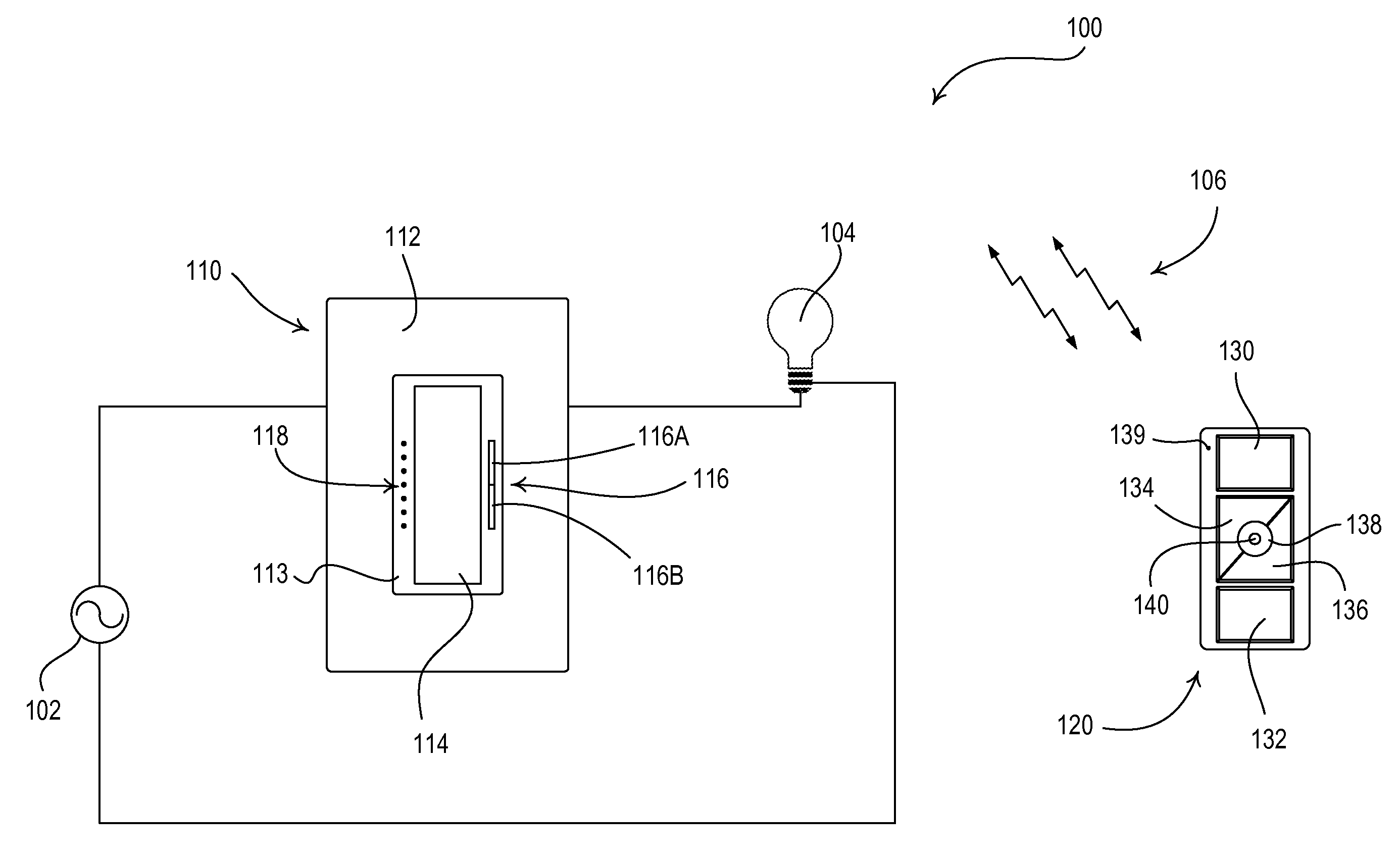
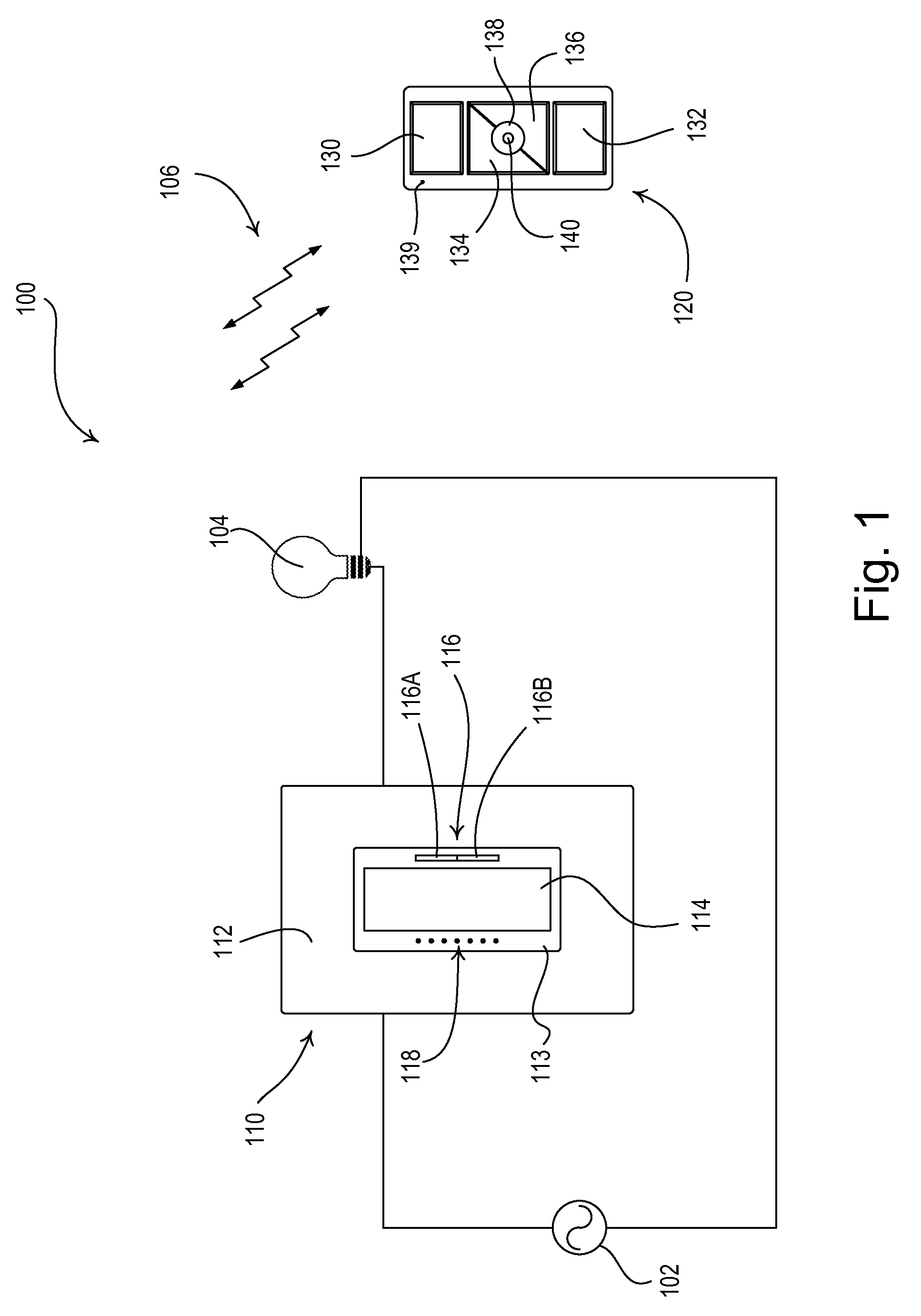
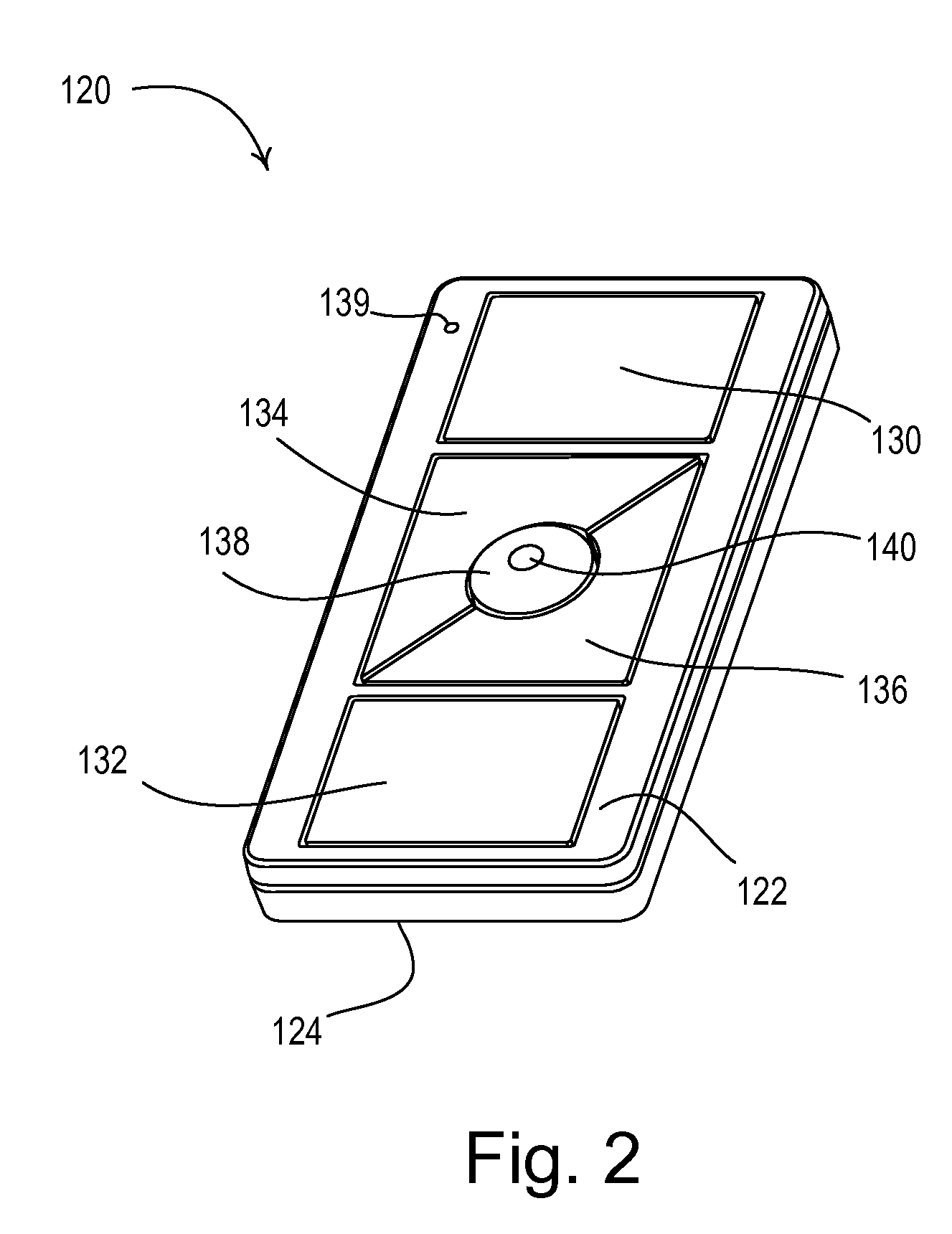
[0050]According to the present invention, the remote control 120 further comprises a night light 140 in the center of the preset button 138. The night light 140 is illuminated to a dim level at all times to allow a user to easily locate the remote control 120 in a dark room. For example, if the remote control 120 is mounted to a wall in a hotel room, an occupant of the hotel room may easily find the remote control after entering the room in the dark. The night light 140 will be described in greater detail below.

[0051]FIG. 4 is a left-side cross-sectional view of the remote control 120 taken through the center of the remote control as shown in FIG. 3. FIG. 5 is an alternate cross-sectional view of the remote control 120 (taken through the diagonal line in FIG. 3) showing the profile of the preset button 138 in greater detail. FIG. 6 is an enlarged perspective view of the preset button 138. The electrical circuitry of the remote control 120 is mounted to a printed circuit board (PCB) ...

third embodiment

[0069]The front surface 582 of the light pipe 580 is textured to diffuse the light, to provide for a constant intensity of illumination across the front surface, and to improve off-angle viewing of the night light 540. FIG. 14 is an enlarged front view of the front surface 582 of the light pipe 580. FIG. 15 is a partial enlarged cross-sectional view of the front surface 582 of the light pipe 580 taken through the center of the light pipe (i.e., taken through the center of the preset button 538 as in FIG. 13). According to the present invention, the front surface 582 of the light pipe 580 has a stepped profile formed by a plurality of concentric circular steps 586. As shown in FIG. 15, each of the steps 586 has an equal width WSTEP (e.g., approximately one one-thousandth of an inch), while each of the steps may have a different height hSTEP because of the convex shape of the front surface 582 of the light pipe 580. Since the front surface 582 of the light pipe 580 has a diameter of a...

fourth embodiment

[0075]FIG. 26 is a perspective view of a wall-mountable load control device (e.g., a dimmer switch 1010) having a circular night light 1040 according to the present invention. The dimmer switch 1010 comprises a bezel 1022, a rear enclosure 1024 for housing the electrical circuitry of the dimmer switch (which will be described in greater detail below with reference to FIG. 27), and a mounting yoke 1026 for mounting the load control device to an electrical wallbox. The dimmer switch 1010 is adapted to be coupled in series electrical connection between an AC power source 1002 (FIG. 27) and an electrical load, e.g., a lighting load 1004 (FIG. 27), for controlling the power delivered to the load. The dimmer switch 1010 comprises an on button 1030, an off button 1032, a raise button 1034, a lower button 1036, and a preset button 1038 to allow a user to control the electrical load. The dimmer switch 1010 may further comprise a linear array of visual indicators 1039 for providing feedback o...


PUM


Abstract

A battery-powered remote control for radiating wireless signals to control a controlled device has a night light that glows whereby it is visible in a darkened room and the battery lasts at least about three years. It also includes a wireless transmitter, a controller, a battery and a control element. The control element generates a signal when activated to cause the controller to operate the wireless transmitter to transmit a wireless signal to control the controlled device. The night light comprises a light emitting diode and a light pipe having a textured front surface. A power supply circuit for the LED provides an LED current from the battery. The LED has a normal operating current range and the LED current is several orders of magnitude below the normal operating current range.

Description

BACKGROUND OF THE INVENTIONCROSS REFERENCE TO RELATED APPLICATIONS[0001]This application is a non-provisional application of commonly-assigned U.S. Provisional Application No. 61 / 485,885, filed May 13, 2011; U.S. Provisional Application No. 61 / 492,051, filed Jun. 1, 2011; and U.S. Provisional Application No. 61 / 606,644, filed Mar. 5, 2012; all entitled BATTERY-POWERED REMOTE CONTROL HAVING A NIGHT LIGHT, the entire disclosures of which are hereby incorporated by reference.FIELD OF THE INVENTION[0002]The present invention relates to a control device, such as a remote control, for a load control system for controlling the amount of power delivered from a source of alternating-current (AC) power to an electrical load, and more particularly, to a battery-powered remote control having a night light.DESCRIPTION OF THE RELATED ART[0003]Control systems for controlling the power delivered from an alternating-current (AC) power source to electrical loads, such as lights, motorized window trea...

Claims


Application Information

Patent Timeline
Patent Type & Authority Applications(United States)
IPC IPC(8): F21L4/00G08C19/16F21V8/00H05B44/00
CPCF21V33/0052Y02B90/224H05B33/0803H05B37/02H05B37/0272H01H9/18H01H21/025H01H2217/024H01H2219/05H01H2219/056H01H2219/062H01H2219/066H01H2221/016H01H2231/032H01H2300/03F21L4/00F21V23/0414F21Y2101/02Y04S20/14H01H9/0235F21Y2115/10H05B47/10H05B47/19Y02B90/20H05B45/325H05B45/37H05B45/395Y02B20/30H05B45/10
Inventor CARMEN, JR., LAWRENCE R.MANN, TIMOTHYMCDONALD, MATTHEW PHILIPSPIRA, JOEL S.
Owner LUTRON TECH CO LLC
Why Eureka
Try Eureka