Image processing method and image processor
a technology of image processing and image processing, applied in the field of inkjet printing apparatus, can solve the problem that the concentration of ink cannot be fully discharged by a single ejection, and achieve the effect of suppressing the density unevenness of an image and high and accurate performan
- Summary
- Abstract
- Description
- Claims
- Application Information
AI Technical Summary
Benefits of technology
Problems solved by technology
Method used
Image

Examples
first embodiment
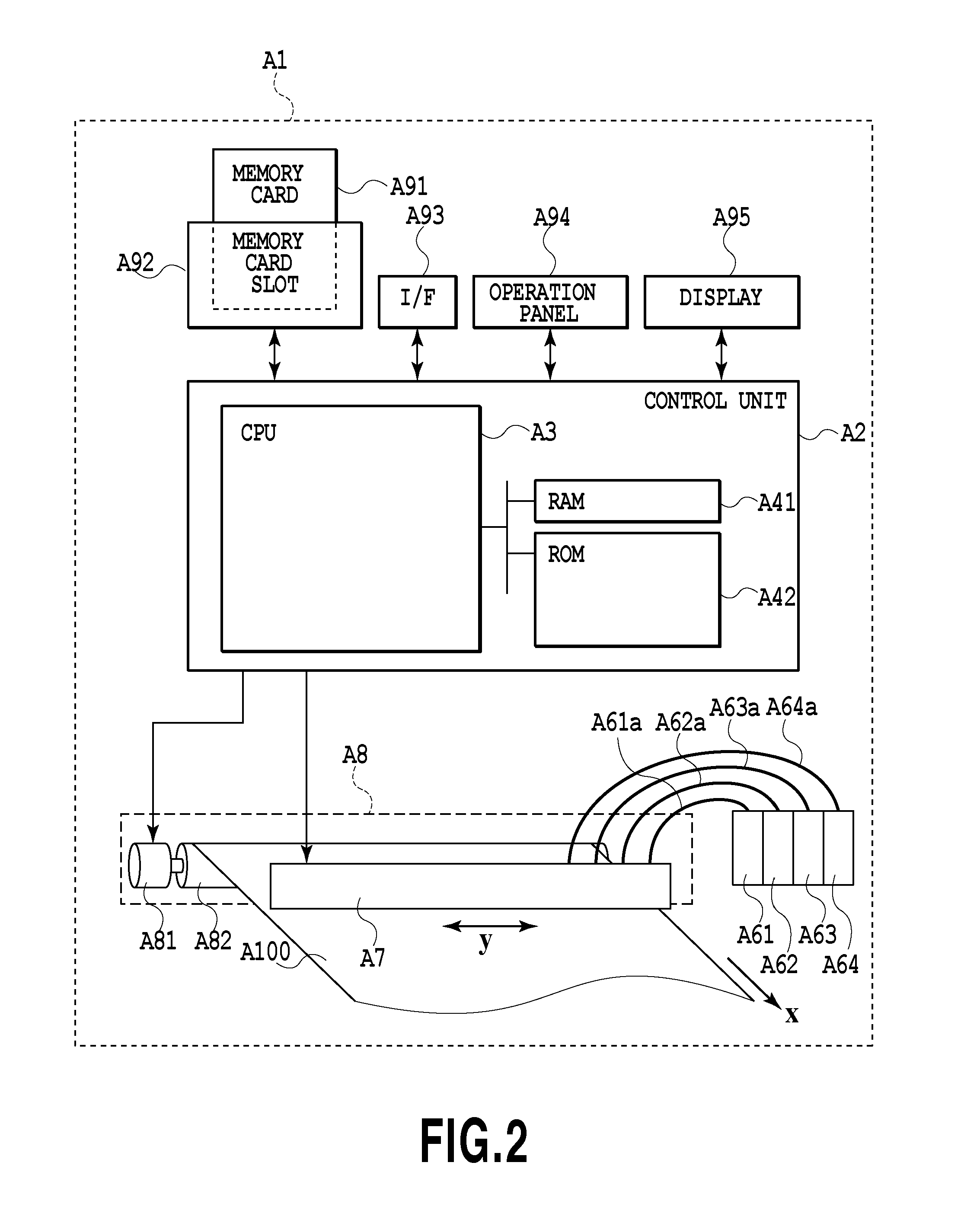
[0028]FIG. 2 is a diagram illustrating a schematic configuration of a printing apparatus A1 used in the present embodiment. The printing apparatus A1 is an inkjet type line printer, and is provided with a control unit A2, ink cartridges A61 to A64, print head A7, print medium conveying mechanism A8, and the like.
[0029]The print head A7 is a full line type print head, and the surface thereof facing the print medium is provided with a plurality of thermal type nozzles that are arranged in a parallel pattern in a Y direction that intersects in a conveying direction (x direction). In the ink cartridges A61 to A64, inks corresponding to cyan, magenta, yellow, and black are respectively contained, and through ink introduction tubes A61a to A64a, supplied to the individual nozzles of the print head A7. Also, according to image data, the inks are ejected from the nozzles to perform printing on the print medium A100 that is conveyed in the x direction at a constant speed. Details of the prin...
second embodiment
[0073]In the present embodiment, described is image processing for the case where the print resolution of the printing apparatus is higher than the image resolution inputted to the image input part. In the present embodiment, the printing apparatus illustrated in FIG. 2 and the print head having a nozzle resolution of 1200 dpi illustrated in FIG. 3 are used, and the resolution of inputted multivalued image data is 600 dpi. That is, quantization is performed to generate data on four pixels having 1200 dpi×1200 dpi for one pixel (600 dpi×600 dpi) in the inputted image data. Also, to print the data on the four pixels, nozzles at the same nozzle positions in two nozzle arrays, i.e., eight nozzles are used, and therefore to obtain a concentration integrated average value, an average of concentration integrated values of the eight nozzles is obtained.
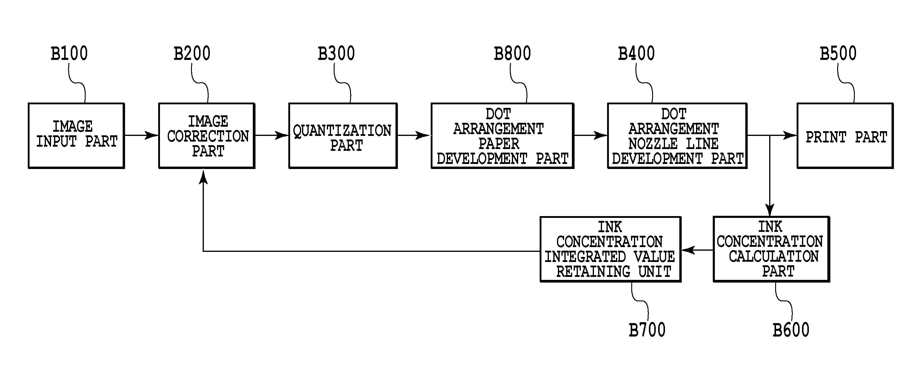
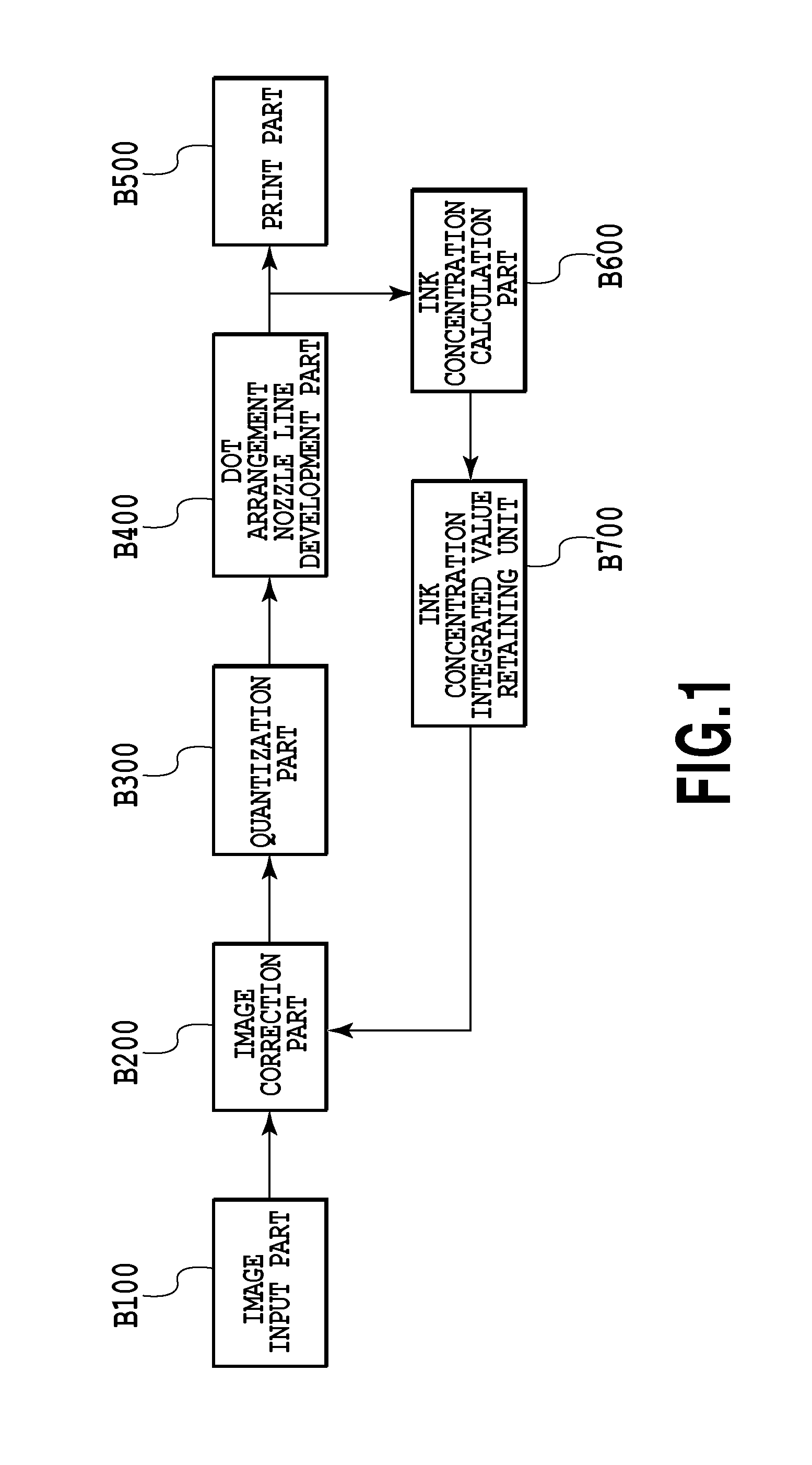
[0074]In the following, FIGS. 10 and 11 are used to describe the image processing in the present embodiment. FIG. 10 is a block diagram for ...
third embodiment
[0085]In the present embodiment, a serial type inkjet printing apparatus is applied.
[0086]FIGS. 13A and 13B are perspective views for explaining the internal configuration of the serial type inkjet printing apparatus used in the present embodiment. FIG. 13A is a configuration diagram of the main body, and FIG. 13B is a configuration diagram of the print cartridge.
[0087]A chassis M3019 contained in the outer case member of the printing apparatus is formed of a plurality of plate-like metal members having predetermined rigidity to constitute a framework of the printing apparatus, and retains respective mechanisms described below. An automatic feeding part M3022 automatically feeds print media into the main body of the apparatus. A conveying part M3029 guides the print media, which are fed one by one from the automatic feeding part M3022 to a predetermined print position, and also guides the print media from the print position to a discharge part M3030. An arrow y represents the convey...
PUM
 Abstract
Description
Claims
Application Information
 - R&D
- Intellectual Property
- Life Sciences
- Materials
- Tech Scout
- Unparalleled Data Quality
- Higher Quality Content
- 60% Fewer Hallucinations
Browse by: Latest US Patents, China's latest patents, Technical Efficacy Thesaurus, Application Domain, Technology Topic, Popular Technical Reports.
© 2025 PatSnap. All rights reserved.Legal|Privacy policy|Modern Slavery Act Transparency Statement|Sitemap|About US| Contact US: help@patsnap.com