Biopsy apparatus and biopsy method

a biopsy apparatus and biopsy method technology, applied in the field of biopsy apparatus and biopsy method, can solve the problems of inability to reduce the amount of applied radiation dose, the inability to reduce the number of captured radiographic images, and the time-consuming examination process, so as to reduce the number of radiographic images, shorten the time required for examination, and reduce the radiation dose

Active Publication Date: 2012-11-15
FUJIFILM CORP
View PDF0 Cites 2 Cited by
  • Summary
  • Abstract
  • Description
  • Claims
  • Application Information

AI Technical Summary

Benefits of technology

[0015]It is an object of the present invention to reduce the number of radiographic images to be captured of an object and to reduce the radiation dose applied to the object to capture radiographic images, while also shortening the time required to examine the object.
[0016]Another object of the present invention is to produce radiographic images of high quality.
[0019]Since the biopsy needle is held obliquely to the radiation reception surface of the radiation detector, the biopsy needle is reliably prevented from overlapping the biopsy region in the radiographic image produced in the scout image capturing mode. Therefore, the radiographic image produced in the scout image capturing mode can also be used as a radiographic image for identifying the three-dimensional position of the biopsy region. In other words, the three-dimensional position of the biopsy region can be identified using two radiographic images, one of which is produced in the scout image capturing mode and the other of which is produced in the stereographic image capturing mode.
[0021]According to the present invention, as described above, since the radiographic image produced in the scout image capturing mode also is used as a radiographic image for identifying the three-dimensional position of the biopsy region, a second radiographic image, which heretofore has been produced in the stereographic image capturing mode, no longer is required. Rather, the three-dimensional position of the object can be identified using the radiographic image produced in the scout image capturing mode together with the first radiographic image produced in the stereographic image capturing mode. As a result, the number of captured radiographic images is reduced, and hence the dose of radiation applied to the breast also is reduced. Inasmuch as the number of captured radiographic images is reduced, the time required to move the radiation source between image capturing modes also is shortened. Therefore, the time required to examine the biopsy region can be shortened, and the object does not need to be held for a long period of time.
[0022]Furthermore, since a grid is used in the scout image capturing mode, the radiographic image produced in the scout image capturing mode is of higher quality than the radiographic image produced in the stereographic image capturing mode. Accordingly, a radiographic image of high quality can be used to identify the three-dimensional position of the biopsy region. In other words, the three-dimensional position of the biopsy region can be identified with high accuracy using both the radiographic image of high quality and the first radiographic image produced in the stereographic image capturing mode.
[0023]According to the present invention, since two radiographic images can be produced in the stereographic image capturing mode, in addition to two radiographic images produced respectively in the scout image capturing mode and the stereographic image capturing mode, the present invention can easily be applied to existing biopsy apparatus.

Problems solved by technology

Therefore, if the doctor or technician who uses the biopsy apparatus is not skilled, then the examination process becomes time-consuming, and tends to hold the object for a long period of time.
According to Japanese Laid-Open Patent Publication No. 2001-504002 (PCT), since eight to ten radiographic images need to be captured in order to identify the position of the biopsy region, the number of captured radiographic images cannot be reduced, and further, the applied radiation dose cannot be reduced.
The angle of the radiation source is set this way because if a scout image capturing mode is performed to irradiate the object with radiation emitted from a radiation source disposed on the perpendicular axis (0°), then the biopsy needle also is imaged in overlapping relation to the biopsy region in the radiographic image captured in the scout image capturing mode, thus making it impossible to identify the position of the biopsy region.
Consequently, the grid cannot be used in the stereographic image capturing mode.
As a result, radiation images captured in the stereographic image capturing mode may possibly be of low quality, due to such scattered radiation.

Method used


Image

  • Biopsy apparatus and biopsy method
  • Biopsy apparatus and biopsy method
  • Biopsy apparatus and biopsy method

Examples


Embodiment Construction

[0037]A biopsy apparatus according to a preferred embodiment of the present invention will be described below in relation to a biopsy method with reference to the drawings.

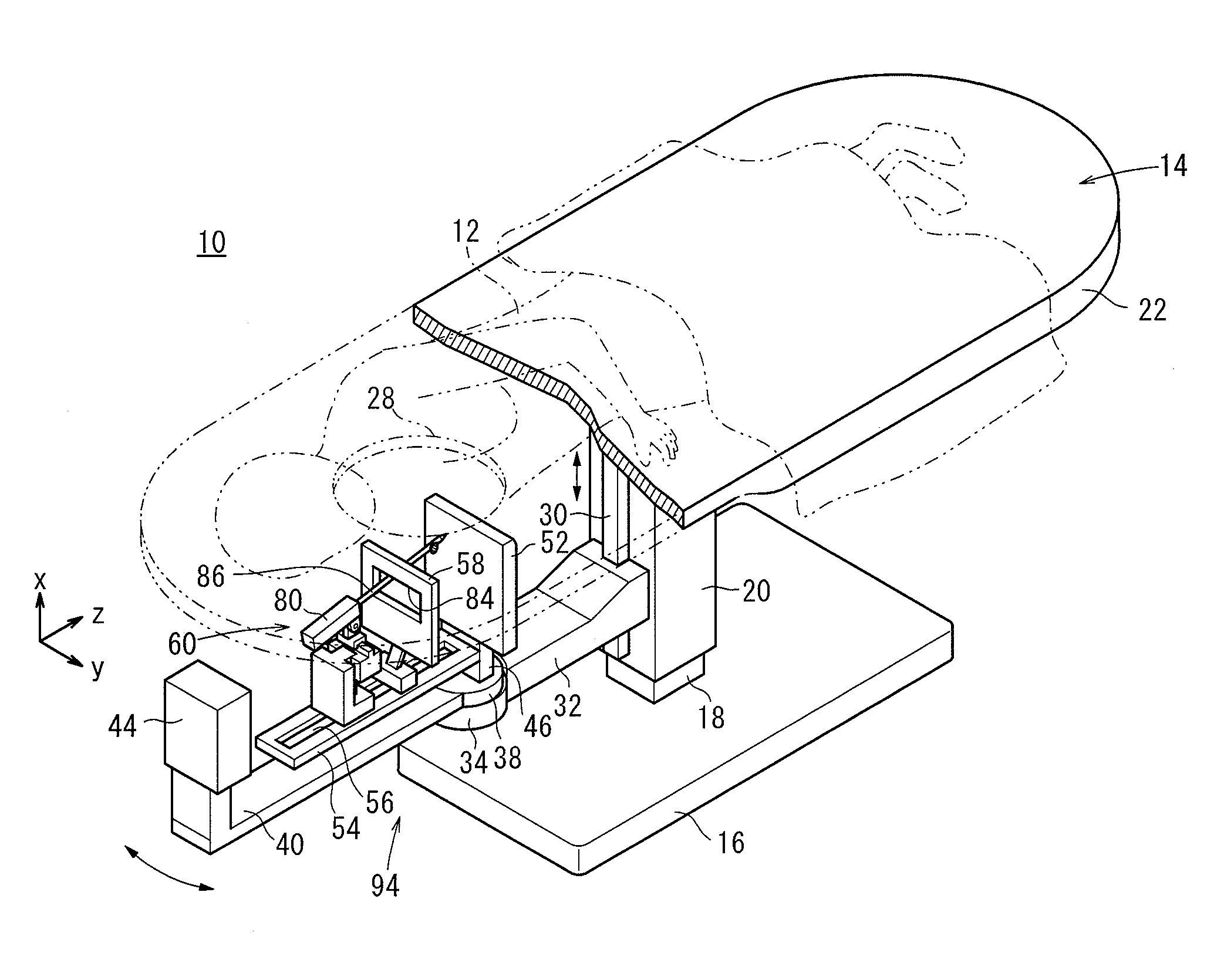
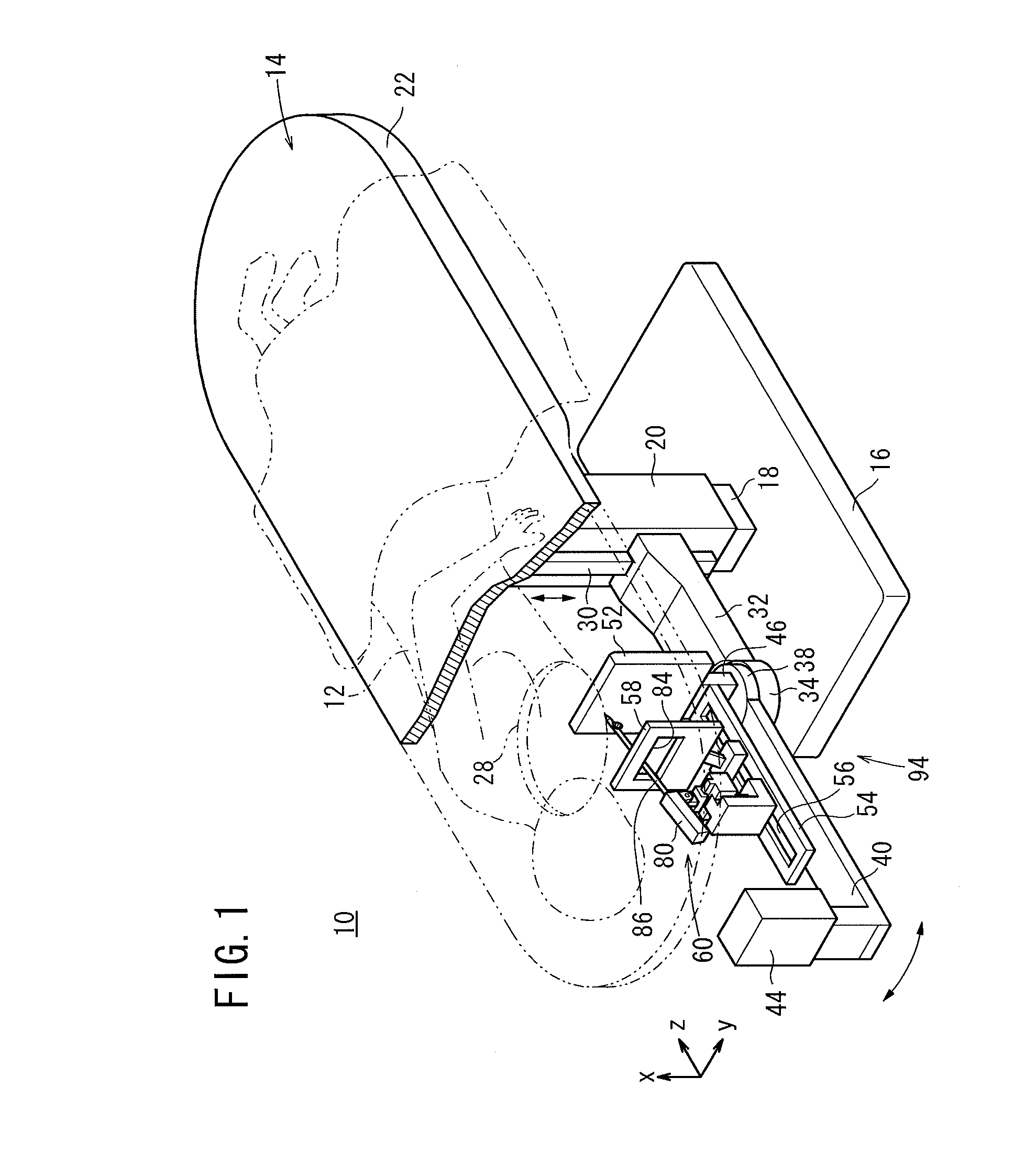
[0038]As shown in FIGS. 1 through 3, a biopsy apparatus 10 according to an embodiment of the present invention includes a bed 14 on which an examinee (subject) 12 lies. The bed 14 comprises a base 16, upstanding support members 18, 20 mounted on the base 16, and a top plate 22 supported on the support members 18, 20. The top plate 22 has an opening 28 defined therein for a breast (an object to be examined) 26 of the examinee 12. The breast hangs down through the opening when the examinee 12 lies on the top plate 22 with the chest wall 24 of the examinee 12 facing downward.

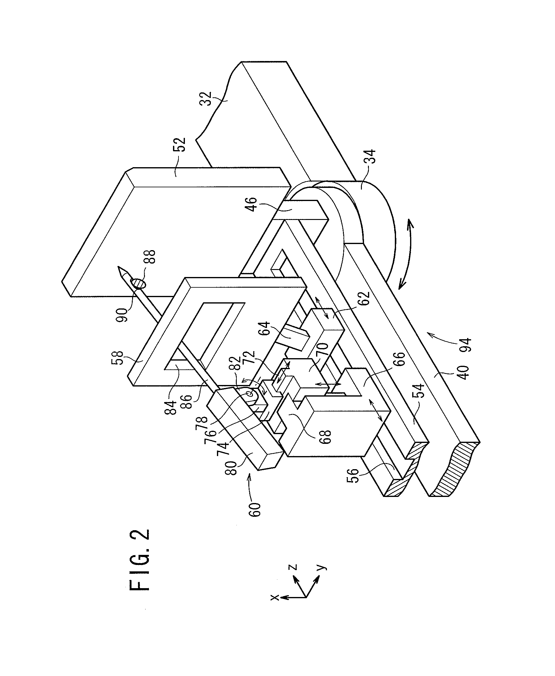
[0039]A support arm 32 is movably mounted on a side surface of the support member 20 for movement along a rail 30, which is attached to the support member 20 and extends vertically in the directions indicated by the arrow x. The support arm 32 ha...


PUM


Abstract

A biopsy apparatus has a biopsy needle, which faces a radiation reception surface of a radiation detector and is held obliquely to the radiation reception surface by a biopsy needle holding mechanism. The biopsy apparatus includes a radiographic image capturing apparatus for capturing two radiographic images. One of the two radiographic images is produced according to a scout image capturing mode or a stereographic image capturing mode, and the other is produced according to the stereographic image capturing mode.

Description

CROSS-REFERENCE TO RELATED APPLICATION[0001]This application a continuation of U.S. patent application Ser. No. 12 / 751,472, filed Mar. 31, 2010, which claims priority to Japanese Patent Application No. 2009-085879, filed on Mar. 31, 2009, each of which is incorporated herein by reference in its entirety.BACKGROUND OF THE INVENTION[0002]1. Field of the Invention[0003]The present invention relates to a biopsy apparatus and a biopsy method for calculating a three-dimensional position of a region to be biopsied (hereinafter referred to as a “biopsy region”) of an object to be examined, based on at least two radiographic images obtained by irradiating the object with radiation from directions that are different from each other, then moving a biopsy needle to the biopsy region based on the calculated three-dimensional position, and removing a tissue sample from the biopsy region.[0004]2. Description of the Related Art[0005]Heretofore, biopsy apparatus have been developed in the art for re...

Claims


Application Information

Patent Timeline
Patent Type & Authority Applications(United States)
IPC IPC(8): A61B10/02A61B6/02
CPCA61B6/502A61B2019/205A61B19/201A61B6/4291A61B90/11A61B90/17
Inventor NAKATA, HAJIME
Owner FUJIFILM CORP
Why Eureka
Try Eureka