This helps you quickly interpret patents by identifying the three key elements:
Problems solved by technology
Method used
Benefits of technology
[0008]In the preferred embodiment of the invention, a carrying case, generally consisting of a two-piece rectangular box, is provided, which box divides into two separate sections upon opening. Each section of the carrying case has a hole approximately center
Problems solved by technology
In the cited examples of prior art and others, when a fish strikes, the line has to turn off the spool, requiring greater pressure or, in some of the prior art, where the spool is in ultimate free flow of position, the line has to be manually placed through a “trigger,” which is extremely sensitive.
Further, a number of the prior art devices require the line spool, and/or trigger device, to be beneath the surface of the water, a significant problem in sub-zero/
Method used
Image
Click on the blue label to locate the original text in one second.
Reading with bidirectional positioning of images and text.
Examples
Embodiment Construction
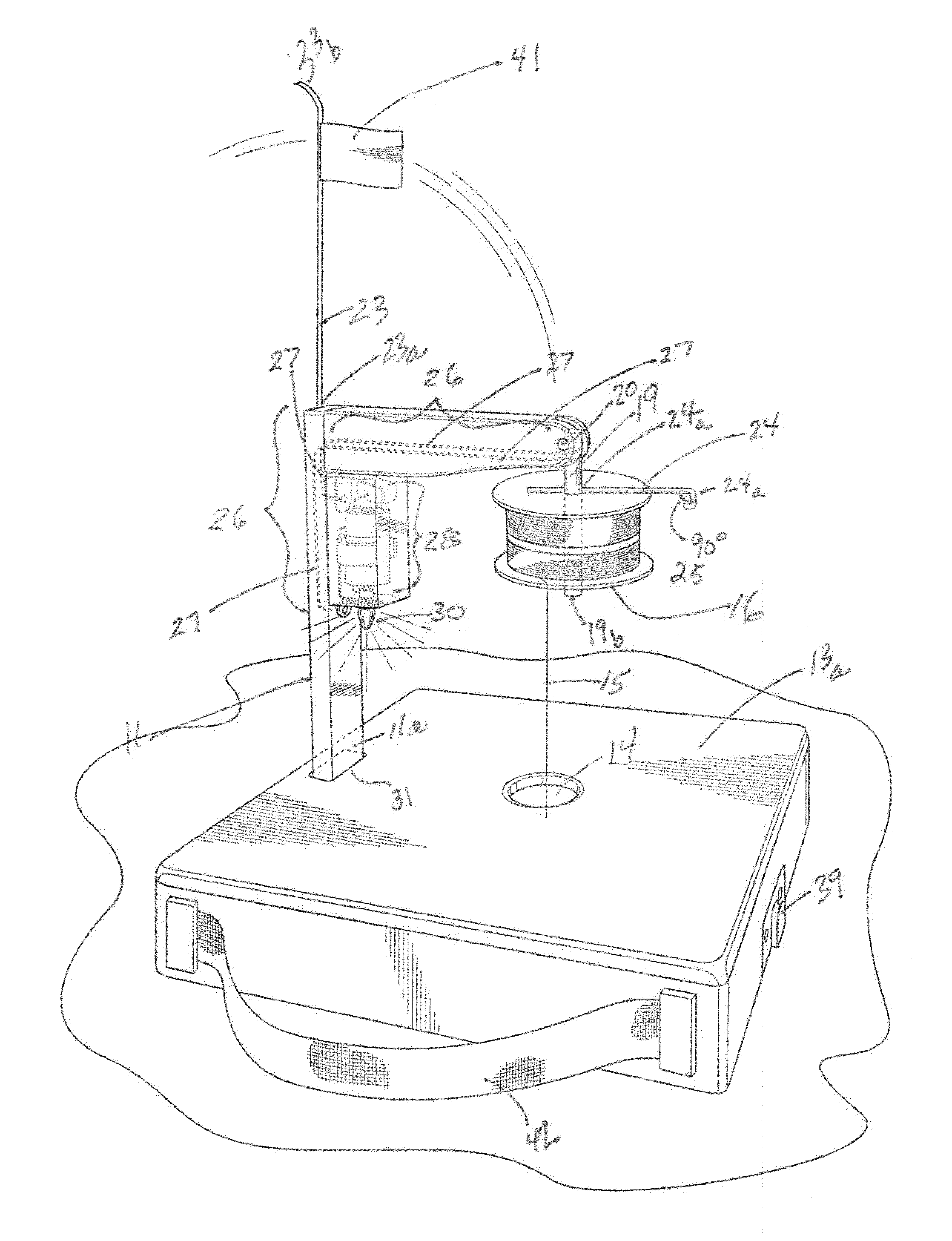
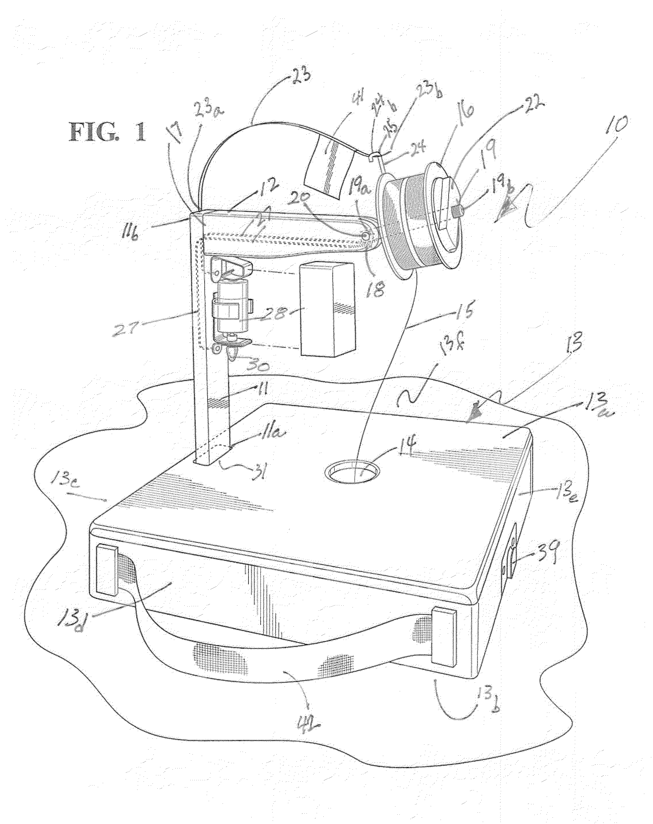
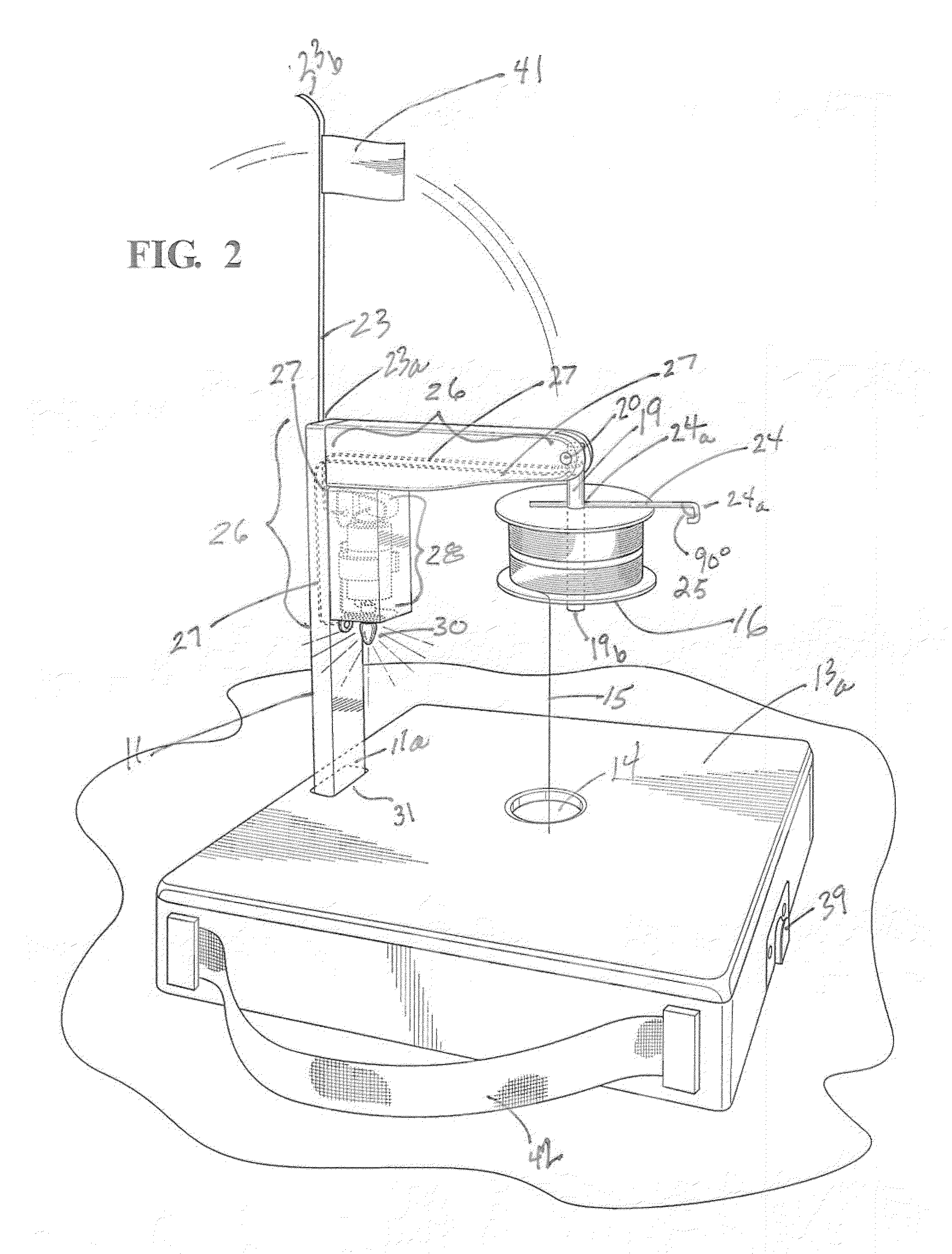
[0020]The invention tip of fishing device 10, broadly considered, has an upright, generally vertically inclined member (or arm) 11, with a lower end 11a and an upper, end 11b. A rigid support arm 12 extends outwardly from said vertical member 11.
[0021]The vertical arm 11 is connected at its lower end 11a to base support 13. In the embodiment of the invention 10 shown in the drawings; base 13 is a box structure as shown in FIGS. 1, 2 and 3, such box structure having a bottom 13a, an open top side 13b, and four sides, 13c, 13d, 13e and 13f. The bottom 13a surface has an aperture 14. As can be seen in FIGS. 1 and 2, the aperture 14 is placed so as to allow a fishing line 15 extending from a spool 16 to extend downwardly through it in fishing operation. Subject to the requirement, that line 15 be allowed to pass through aperture 14 in a substantially downwardly vertical direction, the shape, size and location on the bottom 13a of base 13 of aperture 14 are not critical to the invention ...
PUM
Abstract
A tip up fishing device with a substantially vertical arm and a substantially horizontal cross arm, a holding pin at its end which pivots from a substantially horizontal position, downwardly, to a substantially vertical position. The pin holds a spool of fishing line, rotatably mounted. A strike of a fish moves the pin from horizontal position to vertical position, moving the spool of line from a substantially vertical inclination of the spool face, with the line under pressure, to a substantially horizontal position of the spool face, allowing the line to pay out without significant resistance. The pivotal movement of the axis pin which holds the spool, from horizontal position to a downward vertical position, triggers both a flag and an electric light notification. The lower end of the upright portion of the rigid support is adaptable to attach to different bases as a means for support.
Description
CROSS-REFERENCE TO RELATED APPLICATIONS[0001]The present application claims the priority of U.S. Provisional Patent Application Ser. No. 61 / 488,316, filed May 20, 2011.BACKGROUND OF THE INVENTION[0002]The utilization of “tip up” device featuring a flag or other signal release activated by the strike of a fish on a bait or lure attached by a fishing line to the tip up device is known. U.S. Pat. No. 7,281,348, to Allen, Jr. et al, for an Ice Fishing Apparatus with Eccentric Release Feature, discloses a tip up device, with a vertically inclined spool, suspended below water level, which, when the spool is caused to rotate, releases a flag; U.S. Pat. No. 7,032,343, to Foss, for an Ice Fishing Tip Up Strike Indicator, discloses a submerged spool with a pendulum switch, which, when a fish strikes, causes a tip up arm to swing into vertical position, and a light is ignited; U.S. Pat. No. 7,008,086, to Kell, for an Electronically Controlled Flashing Light and RF transmitter for ice fishing t...
Claims
Application Information
Patent Timeline
Application Date:The date an application was filed.
Publication Date:The date a patent or application was officially published.
First Publication Date:The earliest publication date of a patent with the same application number.
Issue Date:Publication date of the patent grant document.
PCT Entry Date:The Entry date of PCT National Phase.
Estimated Expiry Date:The statutory expiry date of a patent right according to the Patent Law, and it is the longest term of protection that the patent right can achieve without the termination of the patent right due to other reasons(Term extension factor has been taken into account ).
Invalid Date:Actual expiry date is based on effective date or publication date of legal transaction data of invalid patent.