
Spin Stabilized And/ Or Drag Stabilized, Blunt Impact Non-Lethal Projectile

a non-lethal and drag stabilized technology, applied in the direction of ammunition projectiles, weapons, training ammunition, etc., can solve the problems of inability to accurately fly and impact beyond 50 meters, damage to conventional non-lethal projectiles, and rapid decrease of hit probability

Inactive Publication Date: 2012-11-22
JONES KENNETH R
View PDF4 Cites 105 Cited by
  • Summary
  • Abstract
  • Description
  • Claims
  • Application Information

AI Technical Summary

Benefits of technology

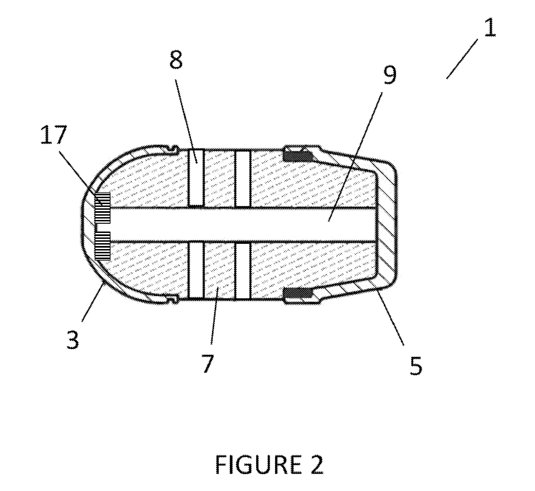
[0015]In a second embodiment of the present invention, the spin stabilized, blunt impact, non-lethal projectile of the first embodiment above is provided, wherein the compressible body further comprises one or more hollow cores disposed within the body portion, said hollow cores extending substantially from the front end to the base. These one or more hollow cores are operable to enable greater deformation of the compressible body and / or allow more compression of the compressible body so as to absorb more energy upon impact of the projectile. In a third embodiment of the present invention, the spin stabilized, blunt impact, non-lethal projectile of the second embodiment above is provided, further comprising one or more perforations disposed within the compressible body, extending from the one or more hollow cores to the outer circumference of the compressible body.
[0026]In a tenth embodiment of the present invention, the spin stabilized, blunt impact, non-lethal projectile of the first embodiment above is provided, further comprising a ring weight disposed integral with, adjacent to or around the projectile, said ring weight operable to increase mass around the circumference of the projectile, thereby increasing gyroscopic stability of the projectile.
[0027]In a eleventh embodiment of the present invention, the spin stabilized, blunt impact, non-lethal projectile of the first embodiment above is provided, wherein the rigid base cap decrease in diameter from a front end thereof to a rear end thereof, such that the rear end of the base cap has a diameter smaller than the front end of the compressible body and maximum diameter of the windscreen. This “boat tail” design helps streamline the projectile to prevent turbulence behind it as it travels, thereby reducing drag.
[0036]In a twentieth embodiment of the present invention, the spin stabilized, blunt impact, non-lethal projectile of the present invention is provided according to the eleventh embodiment, in which a ring weight is disposed integral with, adjacent to or around the projectile, and said ring weight is operable to increase mass around the circumference of the projectile, thereby increasing gyroscopic stability of the projectile.

Problems solved by technology

However, hit probability diminishes rapidly when attempting to engage beyond these ranges.
This is due to inconsistent aerodynamic forces generated by unstable, and possibly inconsistent, projectile shapes.
It was designed for short range use and is incapable of precision flight and impact utility out beyond 50 meters.
Specifically, although the M1006 will fly farther than 50 m, it hits the target with so little force (i.e., so little kinetic energy is delivered), it is useless.
In addition, due to the non-rigid nose (and sometimes base), such conventional non-lethal projectiles are damaged by the weapon by forces exerted thereon in the breach, as well as have deficient aerodynamic characteristics during flight.
This generally produces large deviations in muzzle velocity and often leaves partially consumed powder in the cartridge case and weapon bore.
Further, as stated above, such conventional non-lethal cartridges are damaged by the forces exerted thereon by the weapon.

Method used


Image

  • Spin Stabilized And/ Or Drag Stabilized, Blunt Impact Non-Lethal Projectile
  • Spin Stabilized And/ Or Drag Stabilized, Blunt Impact Non-Lethal Projectile
  • Spin Stabilized And/ Or Drag Stabilized, Blunt Impact Non-Lethal Projectile

Examples


Embodiment Construction

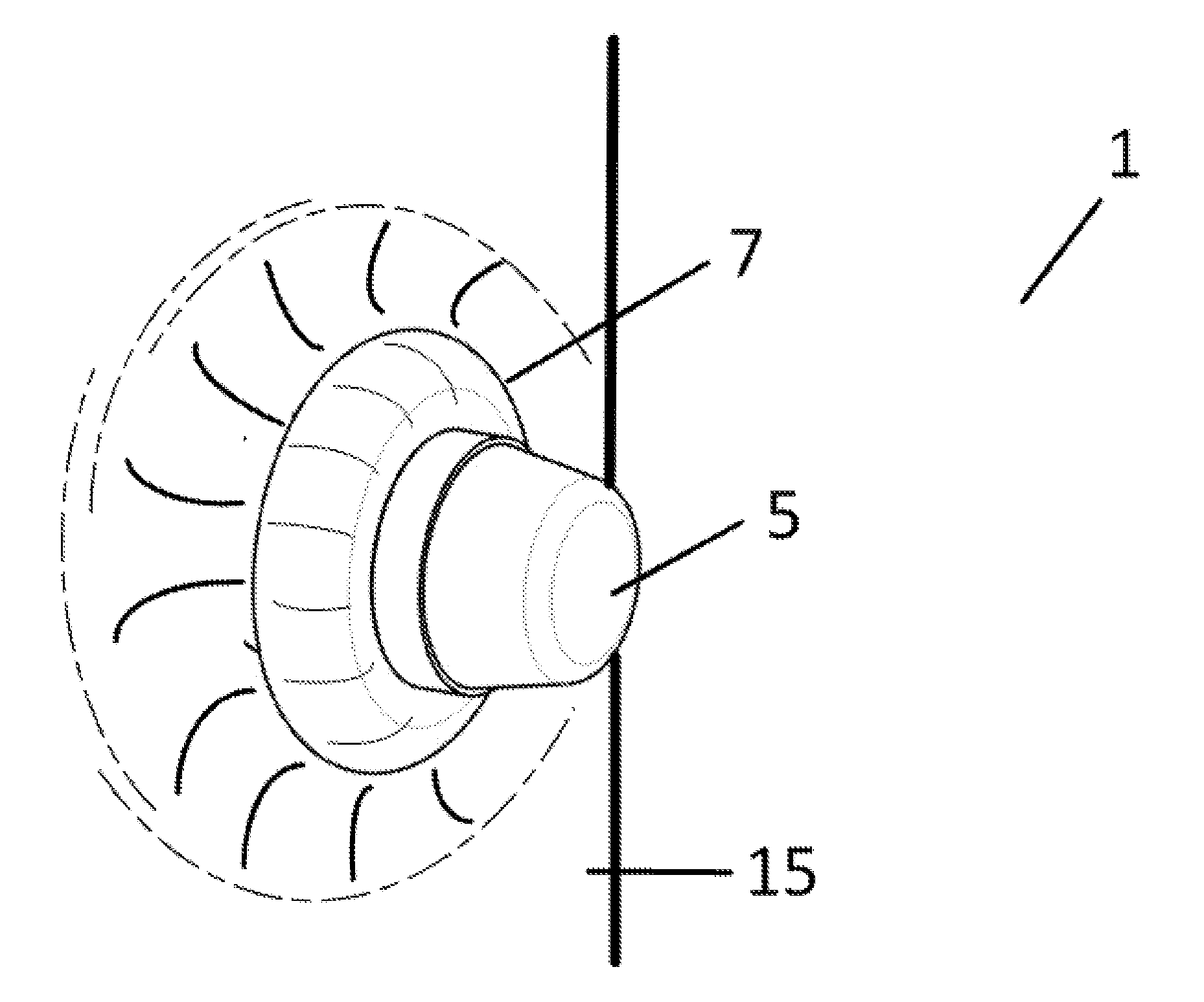
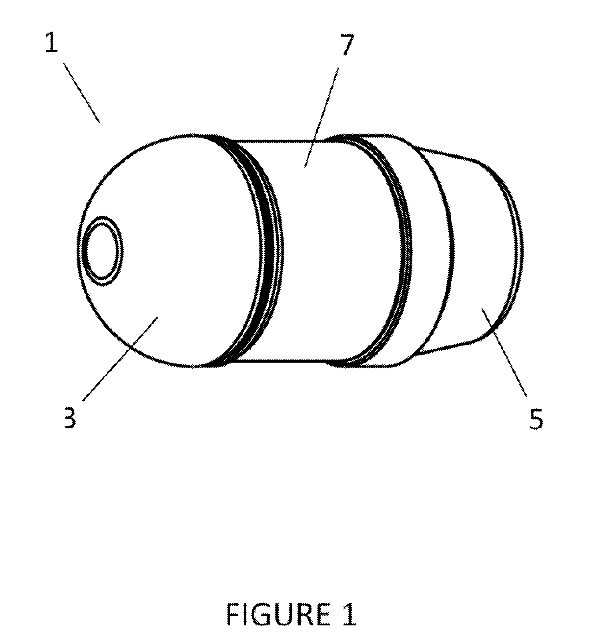
[0070]The present invention provides a spin stabilized, blunt impact, non-lethal projectile, as well as a drag stabilized, blunt impact, non-lethal projectile, both capable of being fired from conventional weapons, such as an M1002 or MK19, without modification thereof. In particular, as illustrated in FIGS. 1-11, the present invention provides a spin stabilized, blunt impact, non-lethal projectile 1 having a rigid windscreen 3, a rigid base cap 5, and a compressible body 7 therebetween. Preferably, the windscreen 3 and base 5 are formed of a rigid yet lightweight material, such as plastic, a composite, a thinly pressed metal, etc. Further, as illustrated in FIG. 3, the windscreen 3 preferably has a tapered nose cone 13 resulting in a blunt impact face, such that impact thereof with a target is non-lethal to the target.

[0071]As mentioned above, both the base cap and windscreen are rigid. This rigidity provides a “double mass” round, i.e., although the rigid windscreen first strikes ...


PUM


Abstract

A spin stabilized and drag-stabilized, blunt impact, non-lethal projectile is provided, having a rigid base and rigid windscreen, with a compressible body therebetween, thereby enabling use thereof in high pressure / compression firing mechanisms, but yet operable to compress / deform upon impact with a target. In particular, a spin stabilized, blunt impact, non-lethal projectile is provided having a rigid windscreen and base, with a compressible body therebetween which compresses / deforms upon impact with a target. In addition, a drag-stabilized version thereof is provided, having canted fins thereon so as to control flight of the projectile via the imposition of drag thereon. Additionally, the projectile is capable of carrying agents, such as crowd control and marking agents, in an agent reservoir, and ejecting same onto a target upon impact.

Description

CROSS REFERENCE TO A RELATED APPLICATIONS [0001]This is a non-provisional application of co-pending provisional application No. 61,468,747, filed Mar. 29, 2011, the contents of which are incorporated herein by reference.BACKGROUND OF THE INVENTION[0002]1. Field of the Invention[0003]A spin stabilized and drag stabilized, blunt impact, non-lethal projectile is provided, having a rigid base, a rigid windscreen and a compressible body therebetween, enabling use thereof in high pressure / compression firing mechanisms, but yet operable to compress / deform upon impact with a target via deformation of the compressible body. In particular, a spin stabilized, blunt impact, non-lethal projectile is provided having a rigid windscreen and base, with a compressible body therebetween which compresses / deforms upon impact with a target.[0004]2. Description of the Related Art[0005]In general, previous non-lethal kinetic energy projectiles have been designed for relatively short range encounters, usual...

Claims


Application Information

Patent Timeline
Patent Type & Authority Applications(United States)
IPC IPC(8): F42B8/14F42B12/50F42B10/26F42B10/22F42B10/06F42B12/02F42B12/40
CPCF42B8/14F42B10/06F42B12/34F42B10/26F42B10/24F42B12/54
Inventor JONES, KENNETH R.
Owner JONES KENNETH R
Learn More