[0005]It is the objective of the present invention to provide a method and a device for forming object hypotheses with the aid of a received signal by at least one
receiver, the method and the device being designed simply and reliably in measurement technology, which makes possible a rapid and accurate analysis for forming object hypotheses.
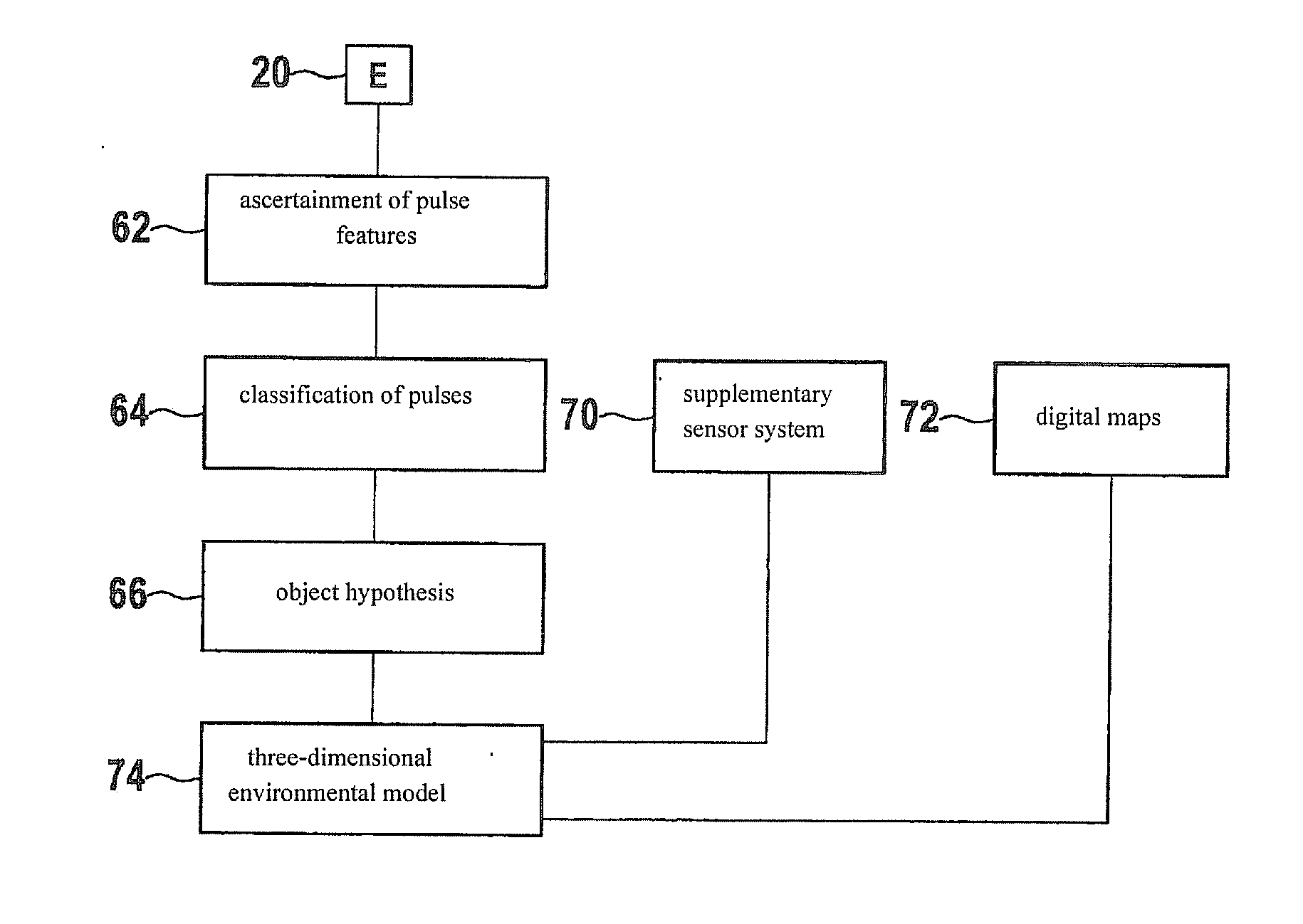
[0006]According to the present invention it is provided that the received signal of the reflected wave be divided up into segments, and from the individual segments, additional data being gathered that are drawn upon for the determination of an object
hypothesis. Because of this, a simple and
rapid processing of the individual segments is made possible, and in addition, the
parallel processing of the individual segments may be taken into consideration.
[0007]It is of particular
advantage that the individual segments are subdivided over time. A
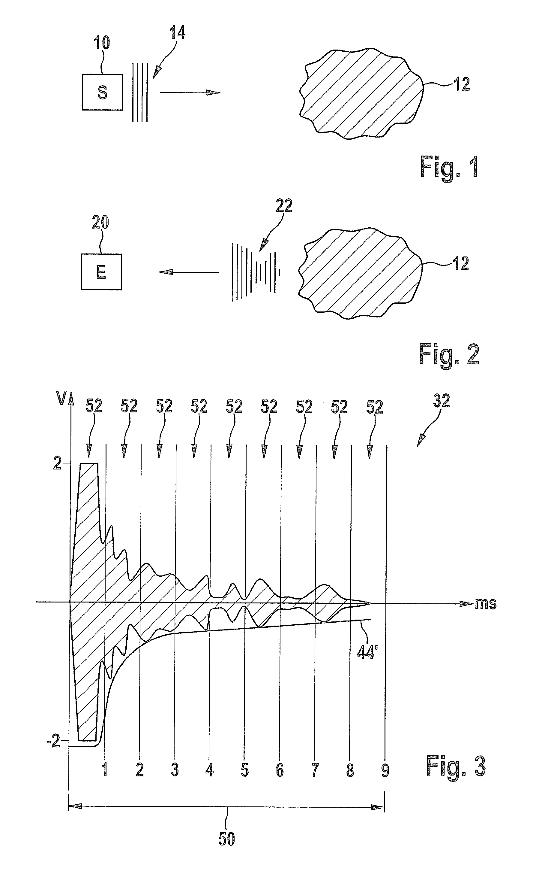
subdivision over time of the received signal, in this instance, is conceivable into equally long and / or unequally long segments. Because of that, the received signal of the reflected wave may be extracted in firmly defined partial signals, so that investigation of the partial, signals is made easier. In addition, observation of significant features of the received signal is possible. Furthermore, the possibility opens up of dropping partial signals, that have no high information content, without obtaining a substantial reduction in the overall information of the received signal. Because of that, efficient and
rapid processing and investigation of the received signal disassembled into partial signals may be ensured. It is additionally conceivable that the signal curve of the received signal is subdivided into individual segments. Thus, data may be ascertained over a certain time interval within a specified
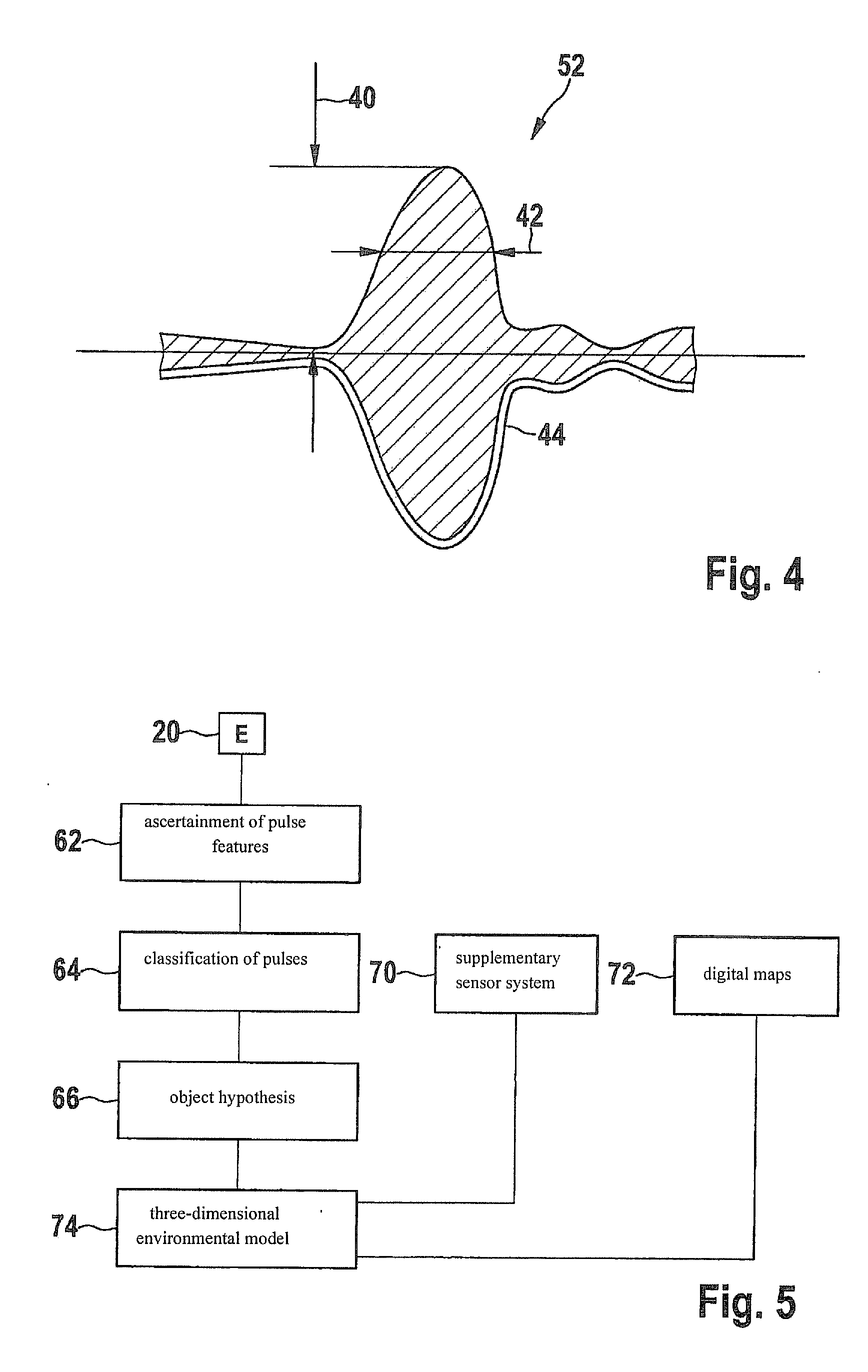
boundary region, which permit additional evidence on the information content of the received signal. In addition, the specified
boundary region may also be limited in time, so that, in the near region of an amplitude, the displacement of the received signal may be investigated more accurately. In addition, the received signal may be subdivided into two-dimensional areas of any size, by subdividing the abscissa and the ordinate into any boundary regions, so that the received signal is able to be disassembled into partial pieces of any size that are able to be drawn upon for closer investigation on their information content. In order to obtain particularly
usable received signals of objects that are at a distance of more than 10 m from the receiver, one may advantageously use electromagnetic transmitters for the emission of transmitting pulses. For distances of objects below 10 m, ultrasonic
waves have proven to be especially expedient.

