
Gate driving circuit and display apparatus having the same

a technology of drive circuit and display apparatus, which is applied in the field of display panel and display apparatus, can solve the problems of deteriorating appearance and increase in costs of display apparatus, and achieve the effect of reducing the number of signal lines and reducing the bezel of display apparatus

Active Publication Date: 2012-11-22
SAMSUNG DISPLAY CO LTD
View PDF5 Cites 32 Cited by
  • Summary
  • Abstract
  • Description
  • Claims
  • Application Information

AI Technical Summary

Benefits of technology

[0010]Exemplary embodiments of the present invention provide a simple structure of a gate driving circuit that can be driven in a forward direction scan mode or a reverse direction scan mode and a display apparatus having the gate driving circuit.
[0022]According to the embodiments of the present invention, only the first metal pattern of the shift register is changed so that the shift register may use the same or substantially the same driving signal for the forward and reverse direction scan modes. An additional driving signal determining the scan mode is unnecessary so that the number of signal lines may be decreased. Therefore, an area in which the gate driving circuit is formed may be decreased so that a bezel of the display apparatus may be reduced.

Problems solved by technology

As a consequence, different timing control parts for controlling the gate driving circuit are used according to the scan mode, thus resulting in an increase in costs.
Therefore, an area in which the gate driving circuit is formed may be increased, thus deteriorating appearance of the display apparatus.

Method used


Image

  • Gate driving circuit and display apparatus having the same
  • Gate driving circuit and display apparatus having the same
  • Gate driving circuit and display apparatus having the same

Examples


Embodiment Construction

[0036]Hereinafter, embodiments of the present invention will be described in detail with reference to the accompanying drawings.

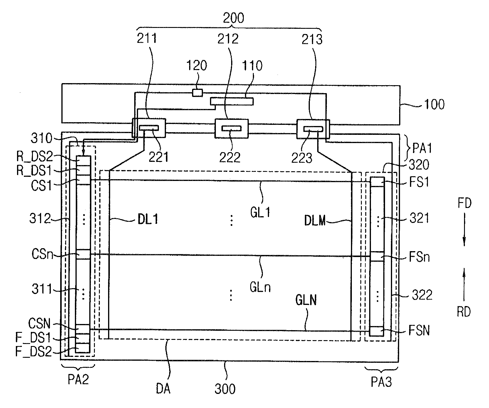
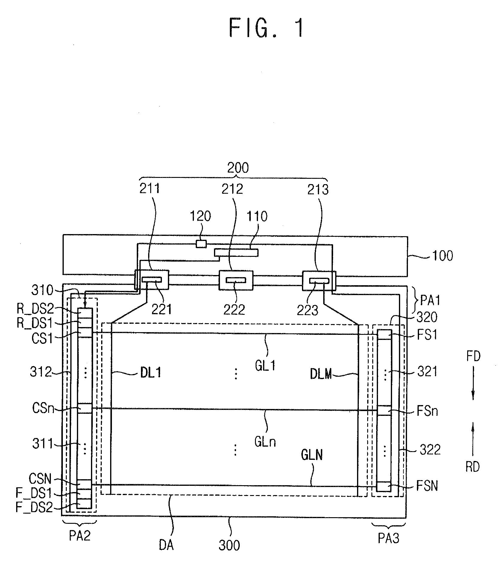
[0037]FIG. 1 is a plan view illustrating a display apparatus according to an exemplary embodiment of the present invention.

[0038]Referring to FIG. 1, the display apparatus includes a printed circuit board (PCB) 100, a data driving circuit 200, and a display panel 300.

[0039]The data driving circuit 200 connected to the PCB 100 is mounted on an upper long side or a lower long side of the display panel 300 according to a scan mode of the display apparatus. For example, in a forward direction scan mode, the data driving circuit 200 connected to the PCB 100 is mounted on the upper long side of the display panel 300 in shown FIG. 1. Alternatively, in a reverse direction scan mode, data driving circuit 200 connected to the PCB 100 is mounted on the lower long side of the display panel 300.

[0040]The PCB 100 includes a timing control part 110 and a voltage generatin...


PUM


Abstract

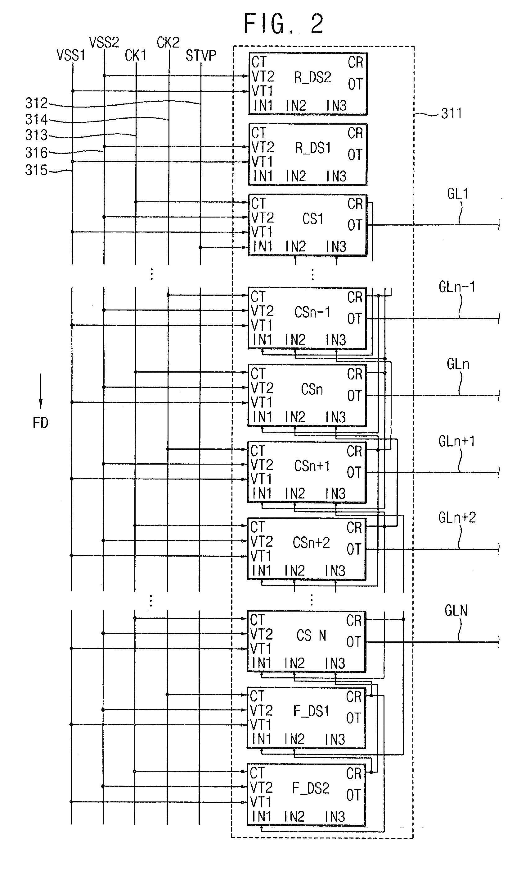
A gate driving circuit includes a shift register and a vertical start line. The shift register includes first to N-th circuit stages sequentially providing first to N-th gate-on signals to first to N-th gate lines, respectively, at least one reverse dummy stage adjacent to the first circuit stage and at least one forward dummy stage adjacent to the N-th circuit stage (N is a natural number). The vertical start line is electrically connected to the first circuit stage or the N-th circuit stage according to a scan direction and transfers a vertical start signal to the first or N-th circuit stage.

Description

PRIORITY STATEMENT[0001]This application claims priority under 35 U.S.C. §119 to Korean Patent Application No. 2011-46737, filed on May 18, 2011 in the Korean Intellectual Property Office, the contents of which are herein incorporated by reference in their entireties.BACKGROUND[0002]1. Technical Field[0003]Exemplary embodiments of the present invention relate to a display panel and a display apparatus having the display panel. More particularly, exemplary embodiments of the present invention relate to a display panel having a gate driving circuit that can simply implement a forward or reverse direction scan mode and a display apparatus having the display panel.[0004]2. Discussion of the Related Art[0005]To decrease a size of a liquid crystal display (LCD) apparatus and to enhance productivity of the LCD apparatus, an amorphous silicon gate (ASG) technology is used in which a gate driving circuit is integrated on a display panel. The gate driving circuit is directly formed on the dis...

Claims


Application Information

Patent Timeline
Patent Type & Authority Applications(United States)
IPC IPC(8): G09G5/00G11C19/00
CPCG09G3/3677G09G2310/0283G09G2300/0426G09G2300/0408G09G2310/0286G09G3/20G09G3/3266
Inventor LEE, JAE-HOONKOO, BON-YONGMOON, SEUNG-HWANLEE, WON-HEE
Owner SAMSUNG DISPLAY CO LTD
Learn More