Combustors with quench inserts

a technology of combustors and inserts, which is applied in the direction of machines/engines, mechanical equipment, lighting and heating apparatus, etc., can solve the problems of adversely affecting the cooling scheme of combustor components

Active Publication Date: 2012-11-29
HONEYWELL INT INC
View PDF9 Cites 58 Cited by
  • Summary
  • Abstract
  • Description
  • Claims
  • Application Information

AI Technical Summary

Problems solved by technology

The design and development of the quench zone geometry is commonly one of the primary challenges in the successful implementation of low-emissions RQL c

Method used


Image

  • Combustors with quench inserts
  • Combustors with quench inserts
  • Combustors with quench inserts

Examples


Embodiment Construction

[0018]The following detailed description is merely exemplary in nature and is not intended to limit the invention or the application and uses of the invention. Furthermore, there is no intention to be bound by any theory presented in the preceding background or the following detailed description.

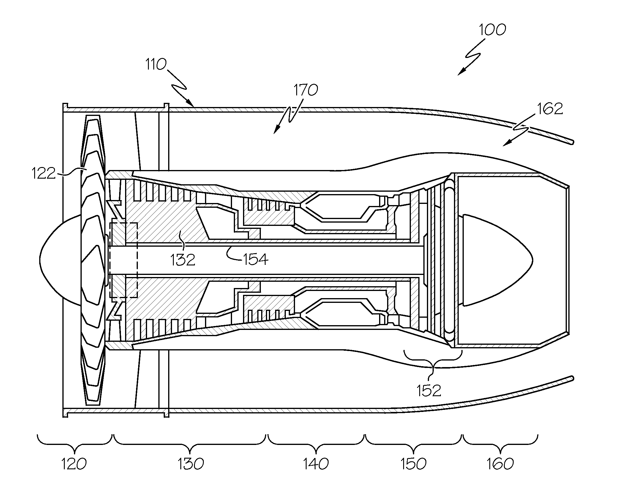
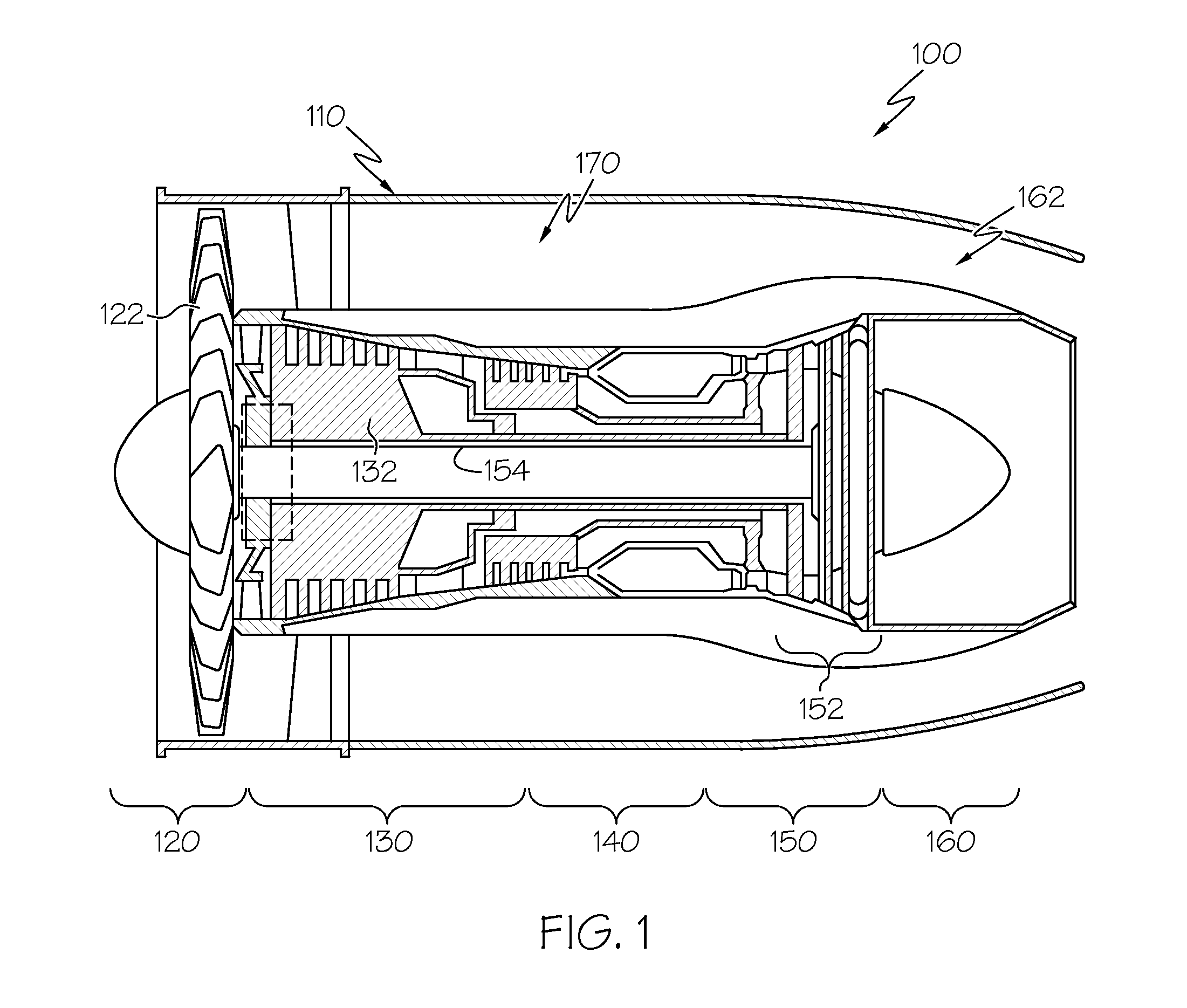
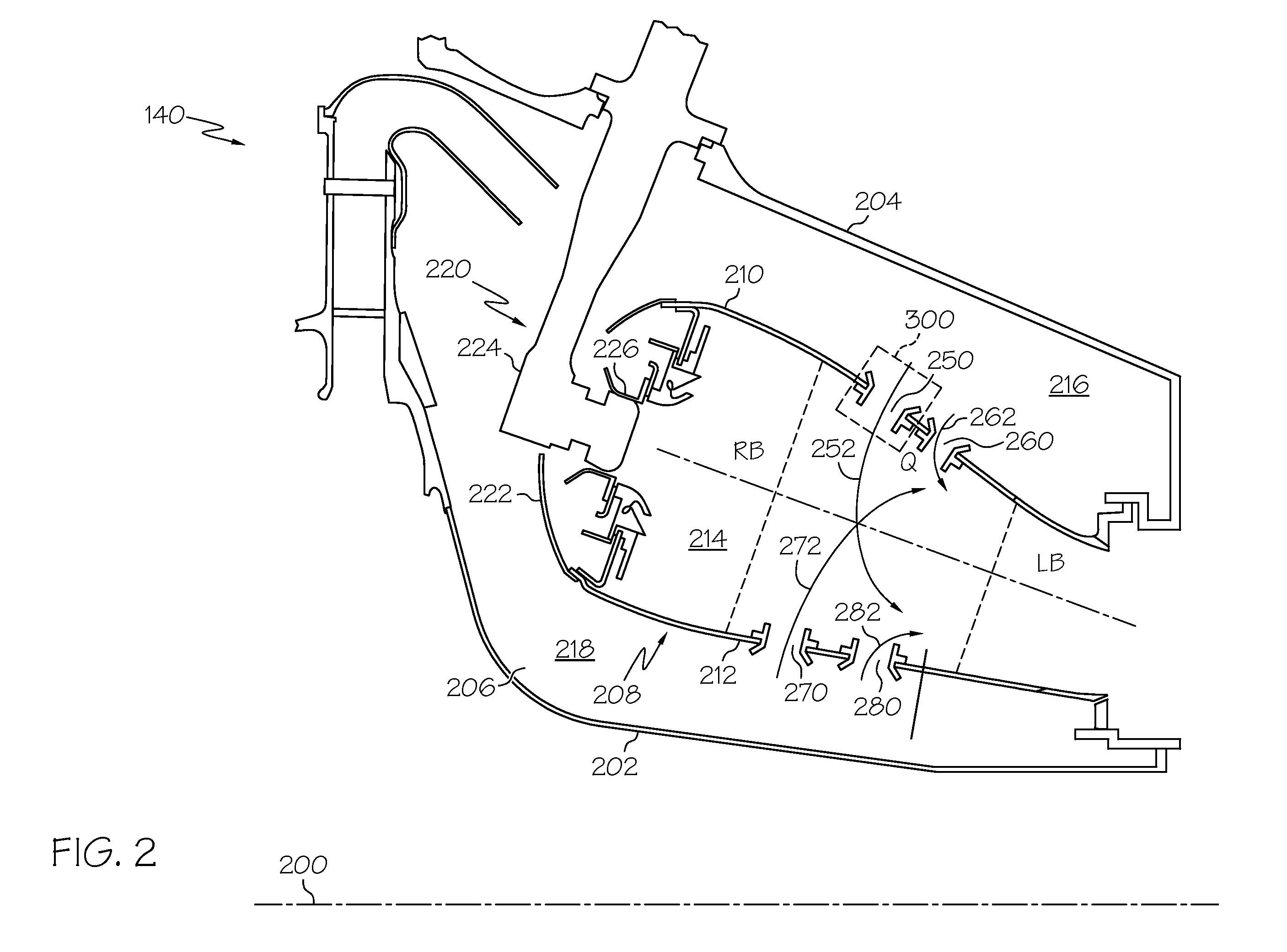
[0019]Exemplary embodiments described herein provide a combustor having single- or double-walled liners with an insert to guide pressurized air through the liner and into the combustion chamber. During installation, each insert generally includes a tubular body portion that is inserted from the hot side through the liner until a shoulder circumscribing the body portion abuts the hot side. A tool then deforms an inlet portion projecting through the cold side to form a flared inlet portion. The flared inlet portion and shoulder capture the liner to retain the insert relative to the liner without welding or other bonding techniques. Cooling holes are then laser drilled into the body of the inse...


PUM

PropertyMeasurementUnit
Temperatureaaaaaaaaaa
Diameteraaaaaaaaaa

Abstract

A combustor is provided for a turbine engine. The combustor includes a first liner having a first hot side and a first cold side; a second liner having a second hot side and a second cold side, the second hot side and the first hot side forming a combustion chamber therebetween. The combustion chamber is configured to receive an air-fuel mixture for combustion therein. The combustor further includes an insert having a body portion extending through the first liner and terminating at a tip, the body portion configured to direct air flow into the combustion chamber. The insert further includes a cooling hole defined in the body portion and configured to direct a first portion of the air flow toward the tip as cooling air.

Description

TECHNICAL FIELD[0001]The following discussion generally relates to gas turbine engine combustors, and more particularly, to combustors with quench inserts and methods for installing the same.BACKGROUND[0002]Gas turbine engines, such as those used to power modern commercial aircraft, typically include a compressor for pressurizing a supply of air, a combustor for burning fuel in the presence of the pressurized air, and a turbine for extracting energy from the resultant combustion gases. The combustor typically includes radially spaced apart inner and outer liners. The inner and outer liners generally define an annular combustion chamber between the compressor and the turbine. A number of circumferentially distributed fuel injectors typically project into the forward end of the combustion chamber to supply the fuel to the combustion chamber, and one or more rows of circumferentially distributed air admission holes in the liners admit air into the combustion chamber for combustion.[000...

Claims


Application Information

Patent Timeline
IPC IPC(8): F23M5/08B21D53/00F23M5/00
CPCF23R3/045Y10T29/49348Y02T50/675F23R3/06Y02T50/60
Inventor RUDRAPATNA, NAGARAJA S.FRYE, LOWELLLANDRAM, WILLIAM
Owner HONEYWELL INT INC
Why Eureka
Try Eureka