Submerged ram air turbine generating system

a technology of air turbine and submerged ram, which is applied in the direction of electric generator control, machine/engine, dynamo-electric converter control, etc., can solve the problems of insufficient power output of existing externally mounted and submerged air turbines, and achieve the effect of reducing drag and minimizing flow separation

Active Publication Date: 2012-11-29
ADVANCED TECH GRP
View PDF4 Cites 14 Cited by
  • Summary
  • Abstract
  • Description
  • Claims
  • Application Information

AI Technical Summary

Benefits of technology

[0008]In alternative embodiments, a closure device in the form of adjustable louvers may be mounted in the submerged inlet upstream from the inlet guide vanes to assist in minimizing flow separation of the air stream in the course of its entry into the interior of the pod, and to close the submerged inlet when the hybrid ram air turbine is not in use for improved aerodynamics and reduced drag. Additionally, the inlet guide vanes may be adjustable to vary the angle at which they direct the air stream to the hybrid ram air turbine.

Problems solved by technology

Existing externally mounted and submerged ram air turbines do not provide sufficient power output, and there is a need for an improved ram air turbine generating system.

Method used


Image

  • Submerged ram air turbine generating system
  • Submerged ram air turbine generating system
  • Submerged ram air turbine generating system

Examples


Embodiment Construction

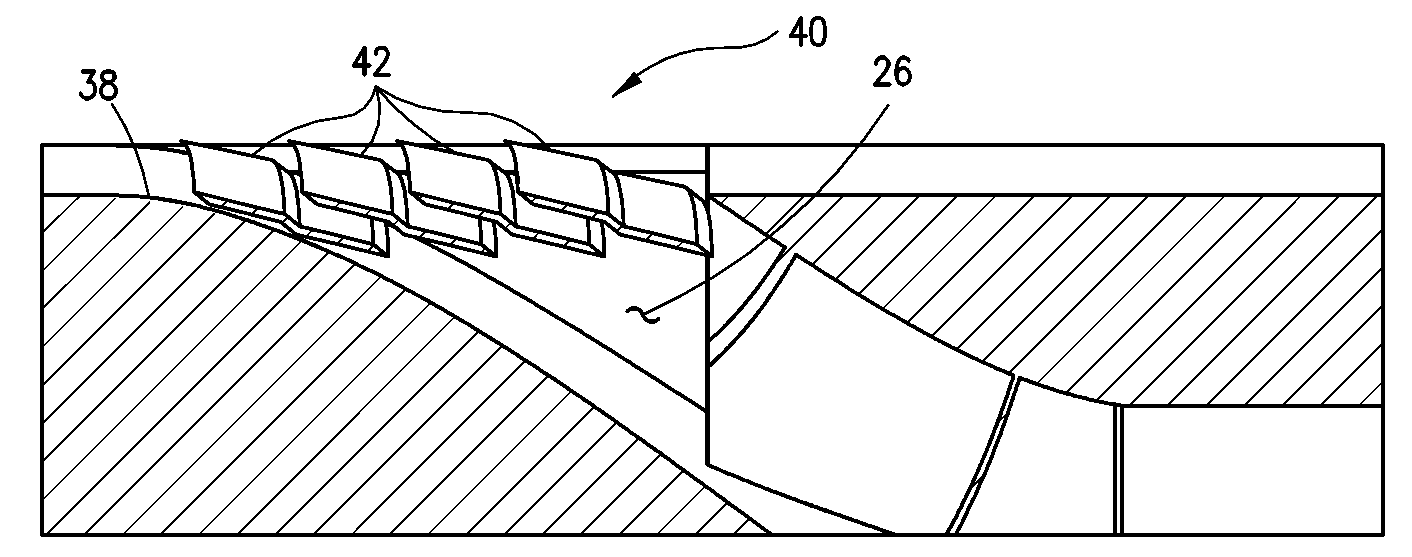
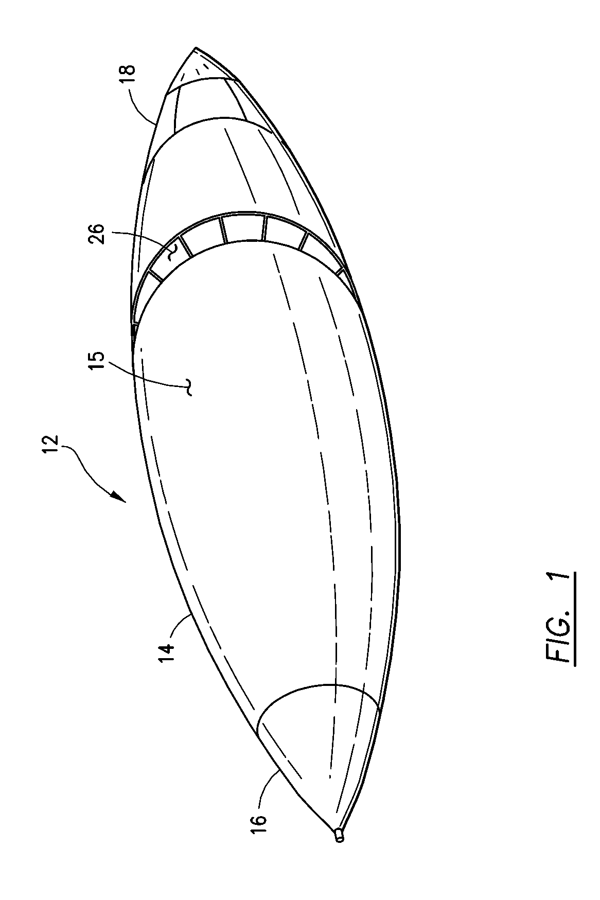
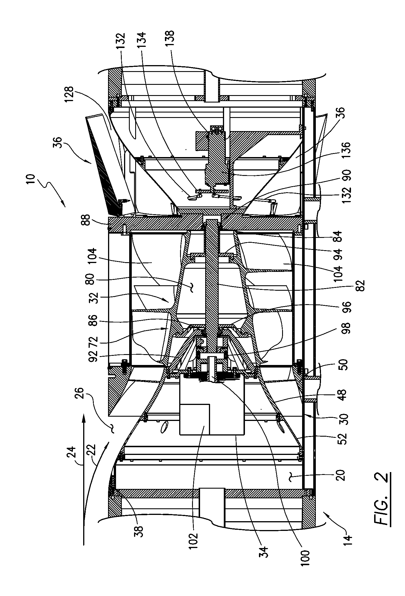
[0029]Referring initially to FIGS. 1 and 2, the submerged ram air turbine generating system 10 of this invention is depicted in one preferred application wherein it is incorporated into a pod 12 typically mounted to the underside of the wing of an aircraft (not shown). The pod 12 generally includes a pod housing 14 having an outer surface 15, a forward end 16, an aft end 18 and a hollow interior 20. For purposes of the present discussion, the terms “forward,”“aft,”“upstream” and “downstream” refer to the direction of a flow of air depicted by arrows 22 and 24 in FIG. 2. In particular, air flowing over the pod 12 during flight of an aircraft impacts the forward end 16 of the pod housing 16 first, and a portion of such flow identifies as air stream 22 enters the pod interior 20 through a submerged inlet 26 of the system 10, discussed below, while the remaining portion of the flow denoted as air stream 24 continues along the outer surface 15 of the pod housing 16. Additionally, the ter...


PUM


Abstract

A submerged ram air turbine generating system adapted for use in a pod mounted to the wing of an aircraft comprises a submerged inlet extending substantially entirely around the outer surface of the pod housing, a stator in the form of adjustable or fixed inlet guide vanes which direct an air stream to a hybrid ram air turbine having alternating turbine blades and splitters, and, a number of adjustable exhaust panels which are movable with respect to one or more exhaust openings in the pod housing.

Description

FEDERALLY SPONSORED RESEARCH[0001]This invention was made with government support under Small Business Innovation Research Contract Nos. N68335-08-C-0276 and N68335-09-C-0313 awarded by the United States Navy. The government has certain rights in the invention.FIELD OF THE INVENTION[0002]This invention relates to a submerged ram air turbine generating system whose operation is based on free stream flow in which power generation is derived from the kinetic energy of a stream of fluid and the system is designed to maximize the velocity and mass flow of the fluid from a submerged inlet through adjustable exhaust panels.BACKGROUND OF THE INVENTION[0003]Ram air turbines are commonly used in military and commercial aircraft to provide a source of hydraulic or electrical power in the event of an emergency. Modern aircraft generate power through the main engines or via an auxiliary power unit such as a fuel-burning turbine typically located in the tail of the aircraft. In most applications ...

Claims


Application Information

Patent Timeline
Patent Type & Authority Applications(United States)
IPC IPC(8): H02K7/18H02P9/48
CPCB64D41/007Y02E10/725F03D9/00F03D1/04F03D9/32F03D9/25F03D80/82F03D80/70F03D15/20Y02E10/72
Inventor JUSTAK, JOHN F.DOUX, CYRILLEMARTYR, STEPHEN
Owner ADVANCED TECH GRP
Why Eureka
Try Eureka