Inherently characteristic of rotating vehicle wheels, and particularly of spoked wheels, aerodynamic resistance, or parasitic drag, is an unwanted source of
energy loss in propelling a vehicle.
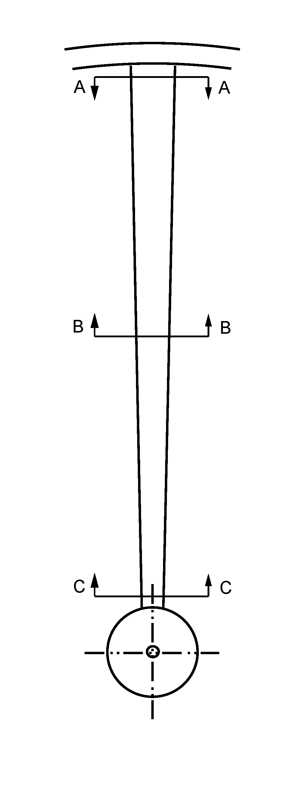
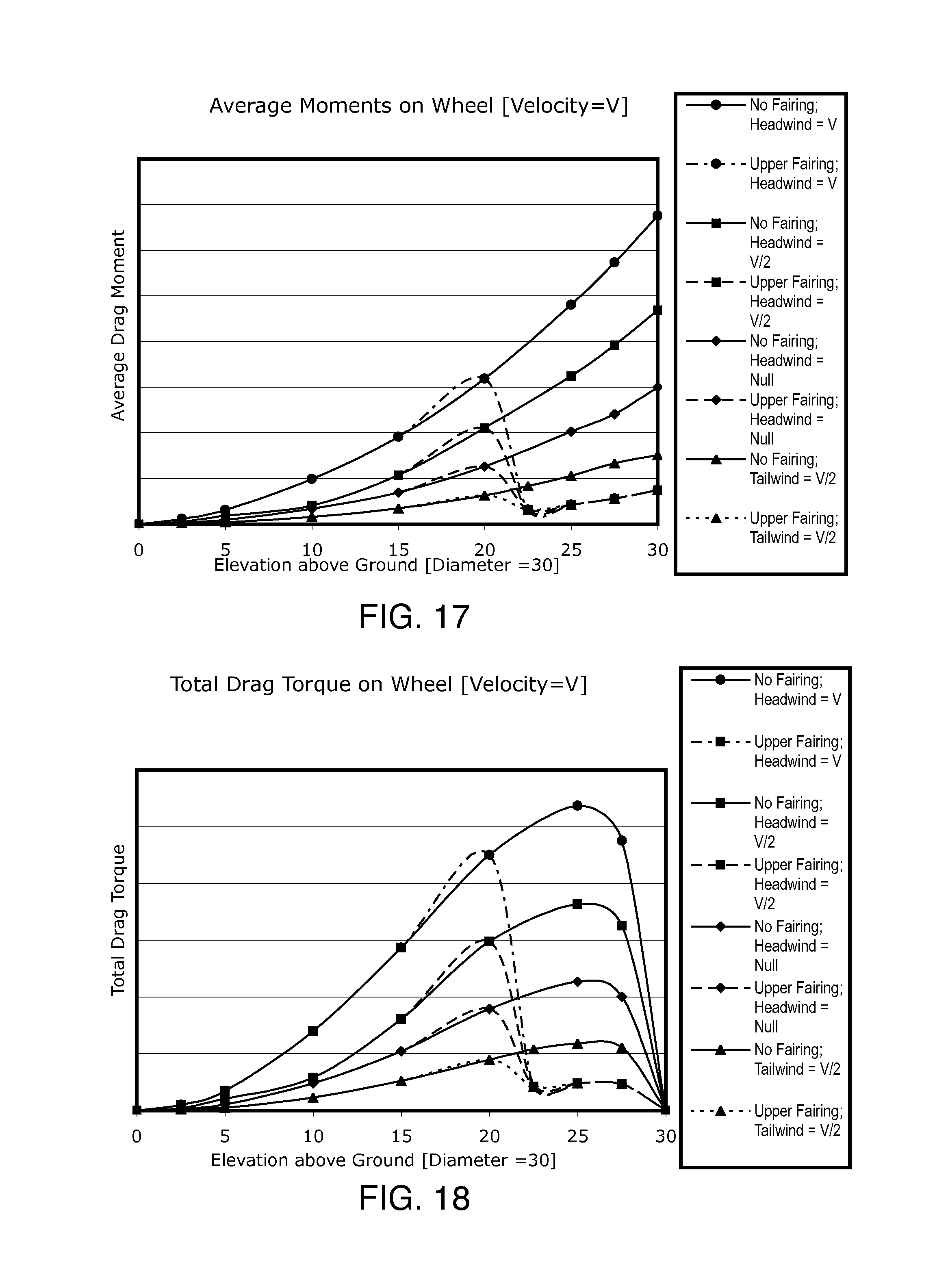
However, as will be shown, frictional drag forces are not uniformly distributed with elevation on the wheel, as they are not uniformly related to the speed of the moving outline of the wheel rim.
The motion of wheel spokes through air creates considerable drag, especially at higher
relative wind speeds.
This
energy loss is particularly critical in both bicycle locomotion and in high-speed vehicle locomotion.
As winds, and particularly headwinds, are a principal source of energy loss in bicycle locomotion, expensive aerodynamic wheel designs have become increasingly popular.
As a result, augmented frictional drag forces present on these larger-surfaced aerodynamic wheel designs tend to offset much of the gains from reduced form drag forces, thereby negating potential reductions in overall drag.
These streamlined spokes suffer from increased design complexity, increased weight and higher costs.
In addition, such bladed designs are more susceptible to
crosswind drag effects: The increased surface area of the bladed
spoke can rapidly increase form drag in the presence of any
crosswind; any
crosswind directed upon the flat portion of the spoke quickly increases pressure drag upon the spoke.
However, most external winds will not be precisely aligned co-directional with the forward motion of the wheel.
Such winds cause a crosswind component to be exerted upon the wheel, leading to flow-separation and thus turbulence—behind the bladed spoke, and thereby generally negate the potential aerodynamic benefit of the bladed-spoke design.
Perhaps a result of these conflicting factors, the bladed spoke has not become the common standard for use in all bicycle competitions.
Wheel covers add weight to the wheel
assembly and can result in more wheel surface area being exposed to winds.
The additional weight on the wheel is detrimental to wheel acceleration, while the large surface area of the cover can increase frictional drag.
In addition, covering large portions of the wheel also increases bicycle susceptibility to crosswind forces, destabilizing the rider.
Perhaps as a result of these conflicting factors, wheel covers have not become the standard equipment for use in all bicycle competitions.
However, these deeper rims—having generally larger rotating surface areas—can dramatically increase friction drag.
As will be shown, friction drag is particularly increased on the expanded upper wheel surfaces, largely negating any potential benefit of the reduced profile drag.
As a result, such deep rims often ride more harshly over bumpy
terrain, and are generally heavier, adding weight to the bicycle, which becomes a drawback when the grade becomes even slightly uphill.
The differences in performance between these various wheel designs appear to only marginal affect the outcome of most races.
As such, they are not necessarily designed to be either forwardly positioned, nor closely fitted to the tire and wheel for aerodynamic shielding purposes.
Perhaps because aerodynamic devices are generally not allowed by rules governing many bicycle competitions, development of fairings for bicycles remains somewhat limited.
Enclosing-type fairings typically have quite large surface areas, which augment frictional drag forces, largely negating any benefit in reducing form drag from streamlining the forward profile of the bicycle.
Frontal wind-deflecting fairings are typically used to reduce form drag on various components on a cycle; however, their greatly expanded surface areas can minimize their effectiveness by introducing greater frictional drag.
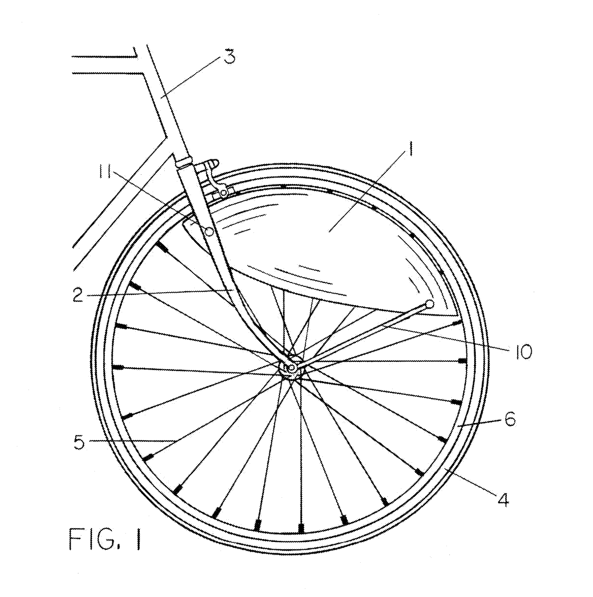
The potential effectiveness of using smaller fairings—having minimal form and friction drag—for shielding specific, critical, drag-sensitive areas of moving wheel surfaces has not been properly recognized.
However, as will be shown, the tested
fender was unnecessarily extensive; its extended design—covering the tire to well below the level of the axle—failed to focus properly on key sources of drag on a typical bicycle wheel.
However, the change in torque measured about the axle on a fixed wheel mounted in an air-
stream—as will be shown—cannot be considered an accurate representation of the change in drag force required to propel the bicycle.
As will be shown, the net drag force is generally not well centered on the rotating bicycle wheel, causing drag forces on the upper wheel to be magnified.
A number of studies of bicycle wheel drag measured in wind tunnels also fail recognize the importance of drag forces on the upper wheel.
Measuring drag on wheels suspended in an airstream will yield incomplete results, particularly for application to moving vehicles.
However, this study also failed to include a
ground plane in contact with the wheel; the wheel remained suspended wind tunnel.
As mentioned, this configuration does not accurately reflect the total retarding force upon a vehicle in motion caused by drag forces on the wheel.
Sunter and Sayers also failed to recognize the magnifying effect that an off-center net drag force on the wheel can have on overall bicycle drag.

