

Endoscope
a technology of endoscope and endoscope, which is applied in the field of endoscope, can solve the problems of disturbance to the user, difficulty in focus for the viewer, and the base of the treatment tool is a disturbance factor for the user, and achieve the effect of reducing the disturbance feeling
- Summary
- Abstract
- Description
- Claims
- Application Information
AI Technical Summary
Benefits of technology
Problems solved by technology
Method used
Image

Examples
first embodiment
[0072]A stereoscopic endoscope system of the present embodiment will be described with reference to FIGS. 4A and 4B. The stereoscopic endoscope system according to the present embodiment is provided with, as main components, a stereoscopic endoscope 1, a stereoscopic display 10, a video processor 20, and an external light source 30.
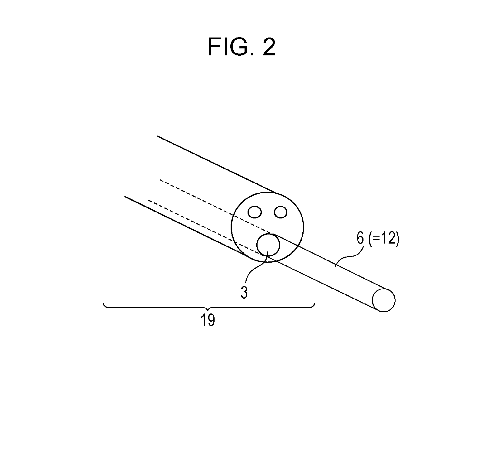
[0073]The stereoscopic endoscope 1 is provided with a manipulation unit 18 which is a handle grasped by a user, and an endoscope tip 19 which is inserted in the body to be observed. The stereoscopic endoscope 1 is capable of capturing two parallax images. The stereoscopic endoscope 1 may be a monocular endoscope which captures two parallax images by different optical paths inside and captures two images with parallax, or may be a pantoscopic endoscope.
[0074]An objective lens and an image capturing element at which an optical image which passed the objective lens is imaged are provided at a tip of the endoscope. CCD (charge-coupled device) image sensors an...
second embodiment
[0100]An endoscope according to a second embodiment is the same as the endoscope according to a first embodiment except that a tip surface of the endoscope is inclined at 21 degrees.
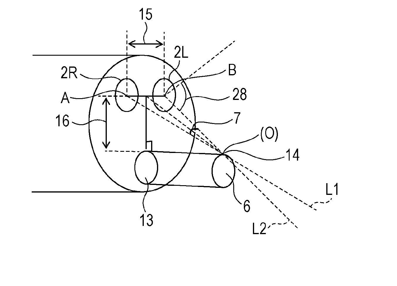
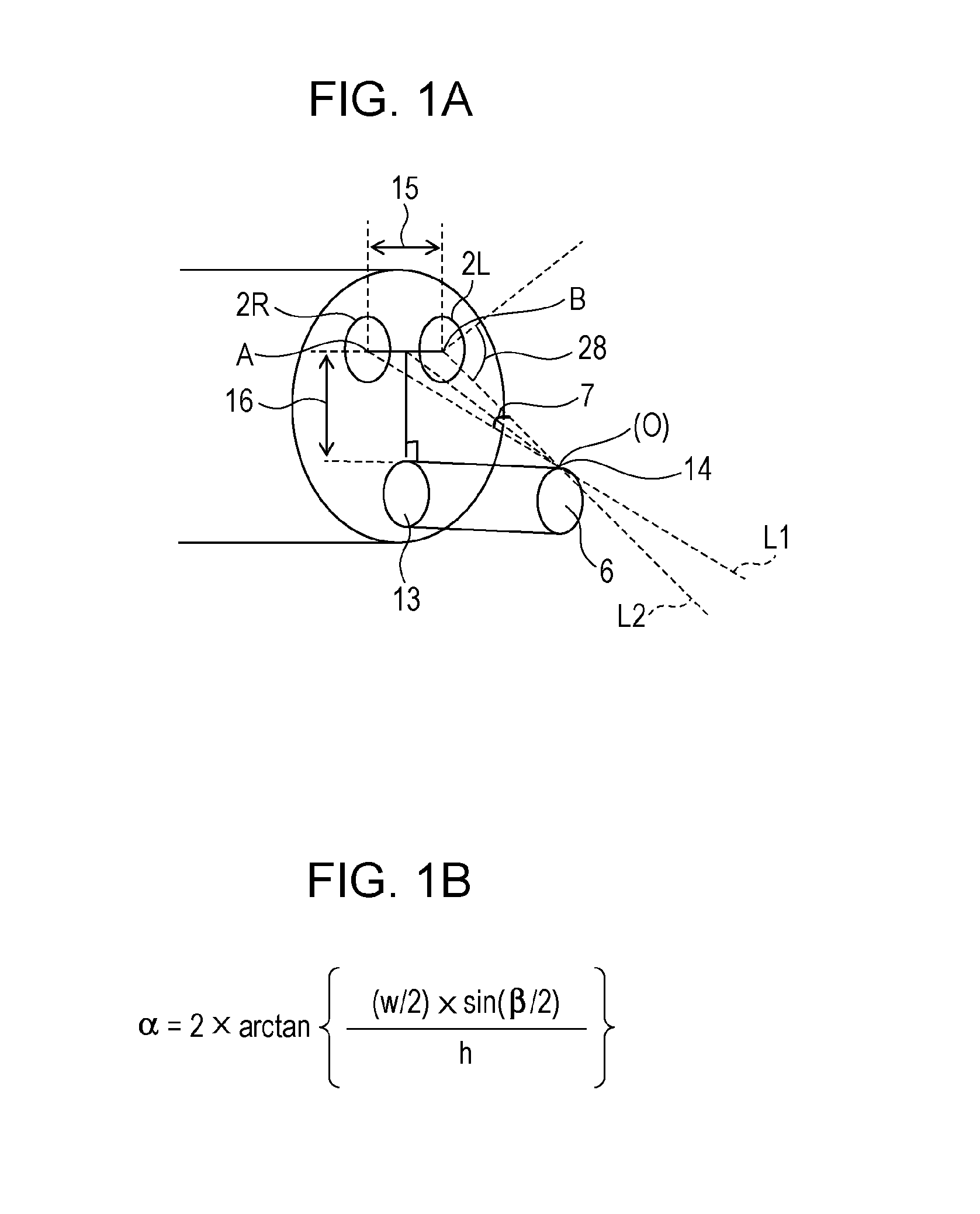
[0101]As illustrated in FIG. 5, a port 13 of a treatment tool insertion channel 3 is provided at a sloped tip surface. FIG. 5 illustrates a state in which the treatment tool has extended to the maximum length thereof. In this state, a point 14 in a movable range 12 (i.e., a locus of the treatment tool) is an arbitrary point on the locus of the treatment tool, and is the position at which the convergence angle becomes the maximum within the visual field.
[0102]The focal length is 50 mm at the center of the objective lens, and the angle of deviation is 30 degrees.
[0103]In this case, the convergence angle becomes the maximum at the position 14 in the movable range of the treatment tool by setting the angle of a port of the treatment tool insertion channel to 23 degrees with respect to the vertical direction....
third embodiment
[0107]The endoscope of a third embodiment is the same as the foregoing embodiments except for the configuration of an endoscope tip.
[0108]As illustrated in FIG. 6, the diameter of the endoscope is 8 mm, the distance 15 between objective lenses is 4 mm, and the distance 16 between the objective lens and the channel 3 is 10 mm. The angle of deviation of a tip surface is set to 30 degrees. A port which is an opening of the treatment tool insertion channel is provided on a side of the endoscope tip. The angle at which the treatment tool extends is 23 degrees with respect to the horizontal plane. The viewing angle of each image capturing unit is 90 degrees.
[0109]In this case, in the movable range of the treatment tool, the convergence angle at the position at which the convergence angle is the maximum is 18 degrees, i.e., not greater than 30 degrees. In this configuration, the image to be displayed is a fused image and, therefore, eyestrain is reduced.
[0110]In the first and second embodi...
PUM
 Abstract
Description
Claims
Application Information