Droop Tester Apparatus and Method

a technology of droop test and apparatus, which is applied in the direction of prosthesis, force measurement by measuring optical property variation, instruments, etc., can solve the problems of high variability and non-uniformity within the sac, and increase the fraction of regurgitants

Active Publication Date: 2012-11-29
MEDTRONIC INC
View PDF2 Cites 69 Cited by
  • Summary
  • Abstract
  • Description
  • Claims
  • Application Information

AI Technical Summary

Benefits of technology

[0008]The transmitter assembly of the system may include a lens arrangement configured to direct light from the sensor onto the target region as a collimated beam of light. The light source may include, for example, a high-intensity GaN green LED.
[0009]In certain embodiments, the transmitter assembly is arranged to direct light at a first side of the target region, and the first image sensor is arranged to sense an image of the target region rel

Problems solved by technology

The material property (mechanical properties such as UTS, percentage strain, Young's Modulus) of pericardial tissue, for example, is highly variable and non-uniform within the sac.
Valves constructed with stiff leaflets combined with droopy leaflets can cause asynchronous valve closure causing regurgitant fractions to increase.

Method used


Image

  • Droop Tester Apparatus and Method
  • Droop Tester Apparatus and Method
  • Droop Tester Apparatus and Method

Examples


Embodiment Construction

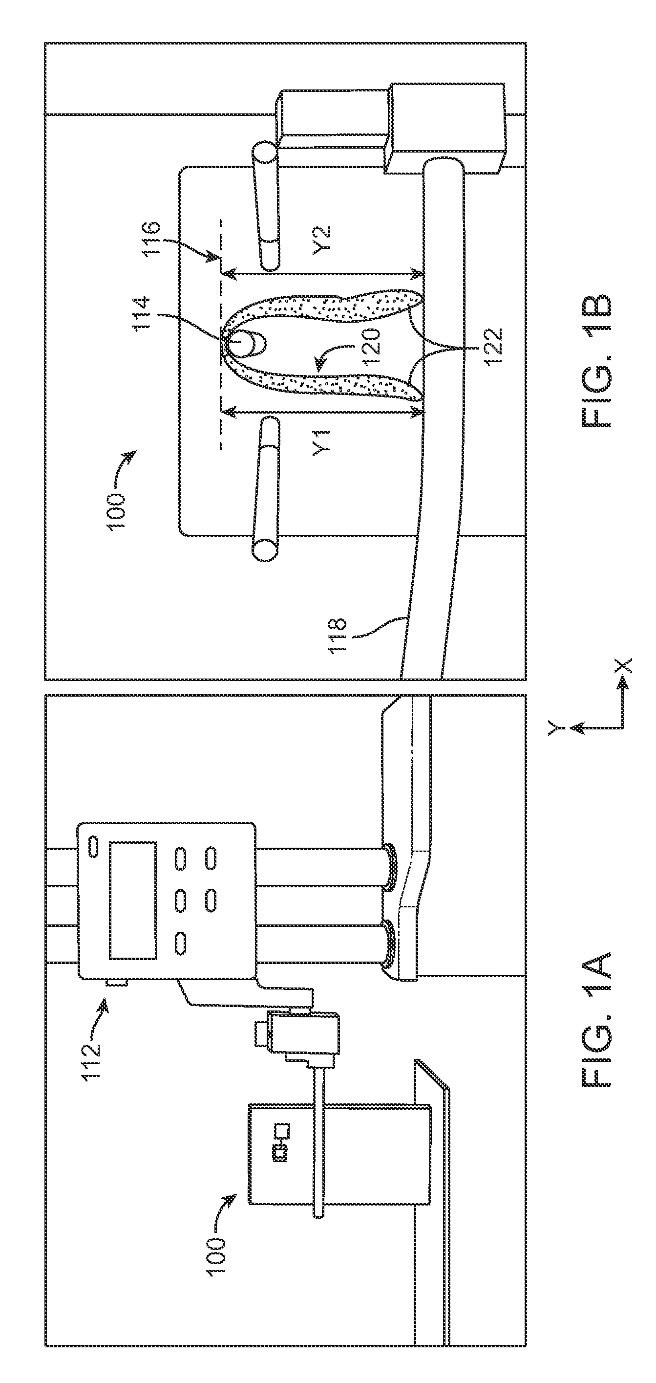
[0020]Several embodiments of droop test apparatuses are described herein that are useful for matching or classifying tissue leaflets (e.g., pericardial tissue from different animal origin or polymer) based on droop values in accordance with principles of the present disclosure. One embodiment of a droop test apparatus 100 is illustrated in FIGS. 1A and 1B. The droop testing apparatus 100 includes a gage 112 and a specimen pin 114. The gage 112 can assume various forms appropriate for detecting or measuring height, such as a Mitutoyo Height gage. More particularly, the specimen pin 114 establishes a baseline 116 from which a measurement of an extent of leaflet droop in a “Y” axis direction (labeled in the figures) is gauged. A height probe 118 of the gage 112 is vertically (in the “Y” axis direction) repositionable with respect to the specimen pin 114. During use, a leaflet 120 is positioned over the specimen pin 114, with the specimen pin 114 located at an approximate centerline of ...


PUM


Abstract

The invention relates to a system for testing heart valve leaflets. The system includes a leaflet support assembly with a support post for receiving and supporting a leaflet to be tested, the post being disposed in a target region of the support assembly. The system also has a transmitter assembly that includes a light source and is configured and arranged to direct light from the light source onto the target region. The system further includes a receiver assembly that has an image sensor configured and arranged to sense an image of the target region and generate image information indicative of the sensed image, such as leaflet droop.

Description

RELATED APPLICATIONS[0001]This application claims the benefit of U.S. Provisional Patent Application No. 61 / 489,834, filed May 25, 2011, which is herein incorporated by reference in its entirety.BACKGROUND[0002]The present disclosure relates generally to apparatuses and methods of screening and selecting leaflets for use in prosthetic heart valves. More particularly, it relates to apparatuses and methods for droop testing leaflets that measures flexural stiffness of the tissue in order to screen leaflets for use in prosthetic heart valves, for example prosthetic aortic transcatheter valves (TCV).[0003]Prosthetic heart valve fabrication, including aortic transcatheter valve (TCV) fabrication, requires leaflets and skirts to be cut in predetermined geometry from animal-derivative tissue (e.g., porcine pericardium) and then sewn together, often as a tri-leaflet valve. Durability and leaflet wear are critical factors in maintaining acceptable performance over the lifetime of the device....

Claims


Application Information

Patent Timeline
IPC IPC(8): H04N7/18
CPCA61F2/2472G01B11/028G01B11/2433G01B11/02A61F2002/7635H04N7/18G01L1/24
Inventor MAJKRZAK, CAROLYNLEE, ROGERGARDE, KSHITIJARICHARDSON, ERICWONG, BENJAMIN
Owner MEDTRONIC INC
Why Eureka
Try Eureka