
Sound box structure for electronic apparatus

a technology of electronic equipment and sound box, which is applied in the direction of transducer details, electrical transducers, electrical apparatus, etc., can solve the problems of not meeting the requirements described above, the shape of the sound box of the electronic equipment is still limited, and the audio quality of the sound box structure of the electron apparatus is improving, so as to enhance the multimedia effects of the electronic apparatus, the effect of increasing the resonating space of the sound box structur

Inactive Publication Date: 2012-11-29
WISTRON CORP
View PDF6 Cites 7 Cited by
  • Summary
  • Abstract
  • Description
  • Claims
  • Application Information

AI Technical Summary

Benefits of technology

The present patent provides a sound box structure for an electronic device that improves the output audio quality and enhances the multimedia effects of the device. This is achieved by combining the original sound box structure with the accommodating space of other electronic devices. The structure includes a resonating cavity, a loudspeaker, and at least one electronic device. The loudspeaker and electronic device are placed in the resonating cavity to increase the resonating space and improve the output audio quality of the sound box structure. This results in a better overall listening experience for the user.

Problems solved by technology

In addition to choosing excellent hi-fi equipment or other playback apparatuses, people are getting picky about the sound quality of the loudspeaker.
Nonetheless, owing to the limitations imposed by technologies, materials, and relevant concepts, the sound boxes of electronic apparatuses are still limited by their design in shapes although they have already made leaps in the development of size and weight.
If sound boxes are designed according to prior art, the requirements described above will never be met.

Method used


Image

  • Sound box structure for electronic apparatus
  • Sound box structure for electronic apparatus
  • Sound box structure for electronic apparatus

Examples


first embodiment

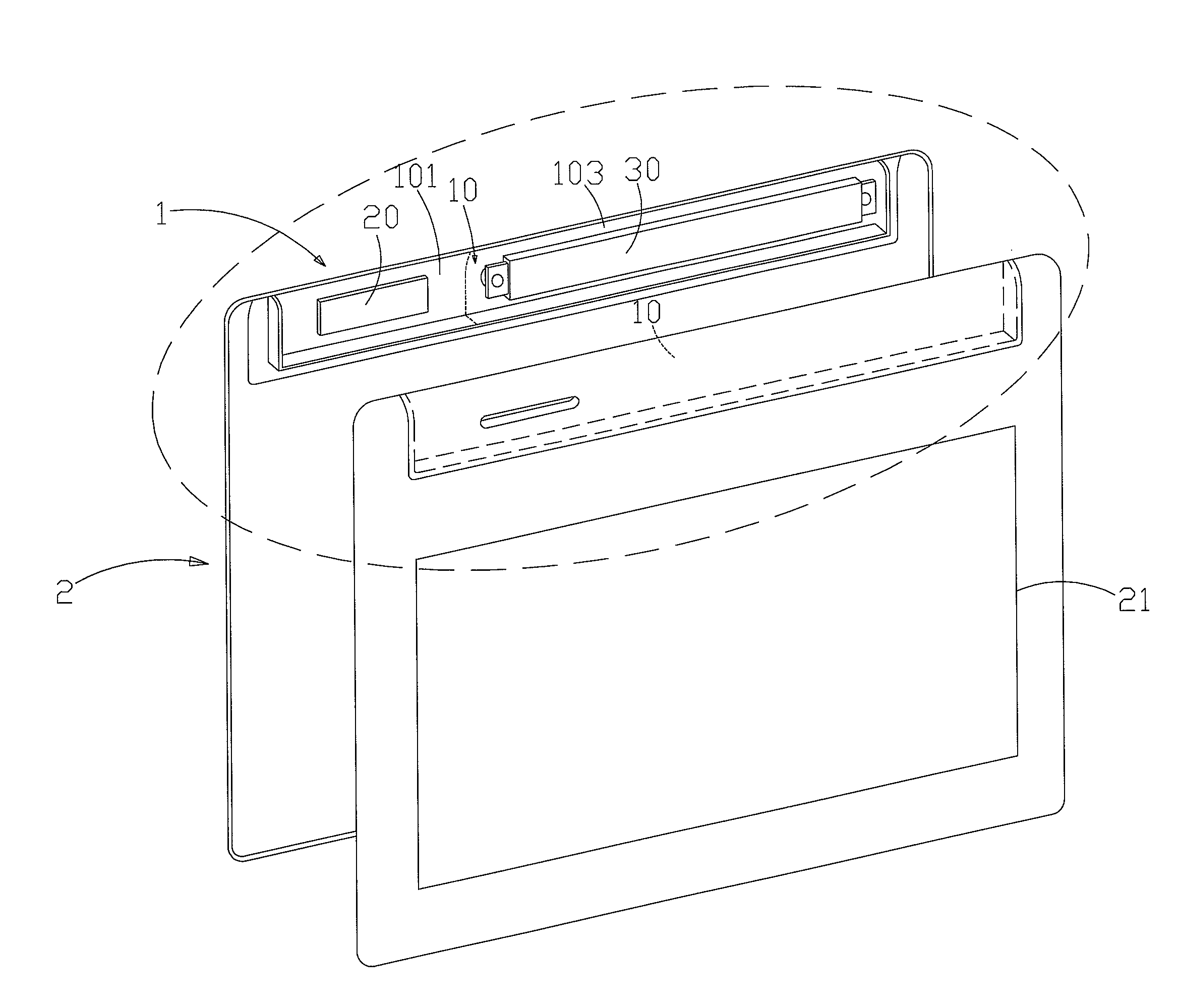
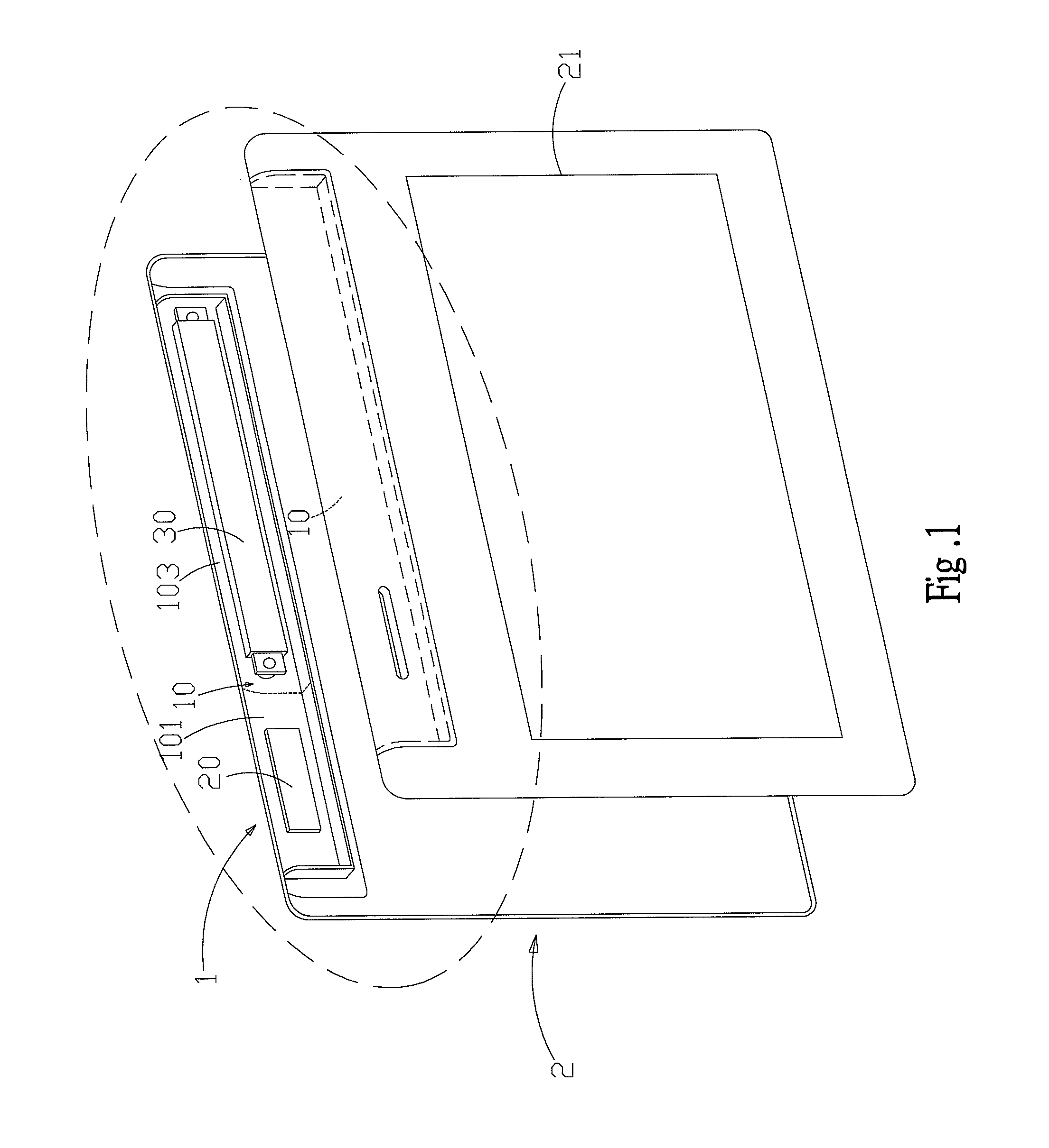
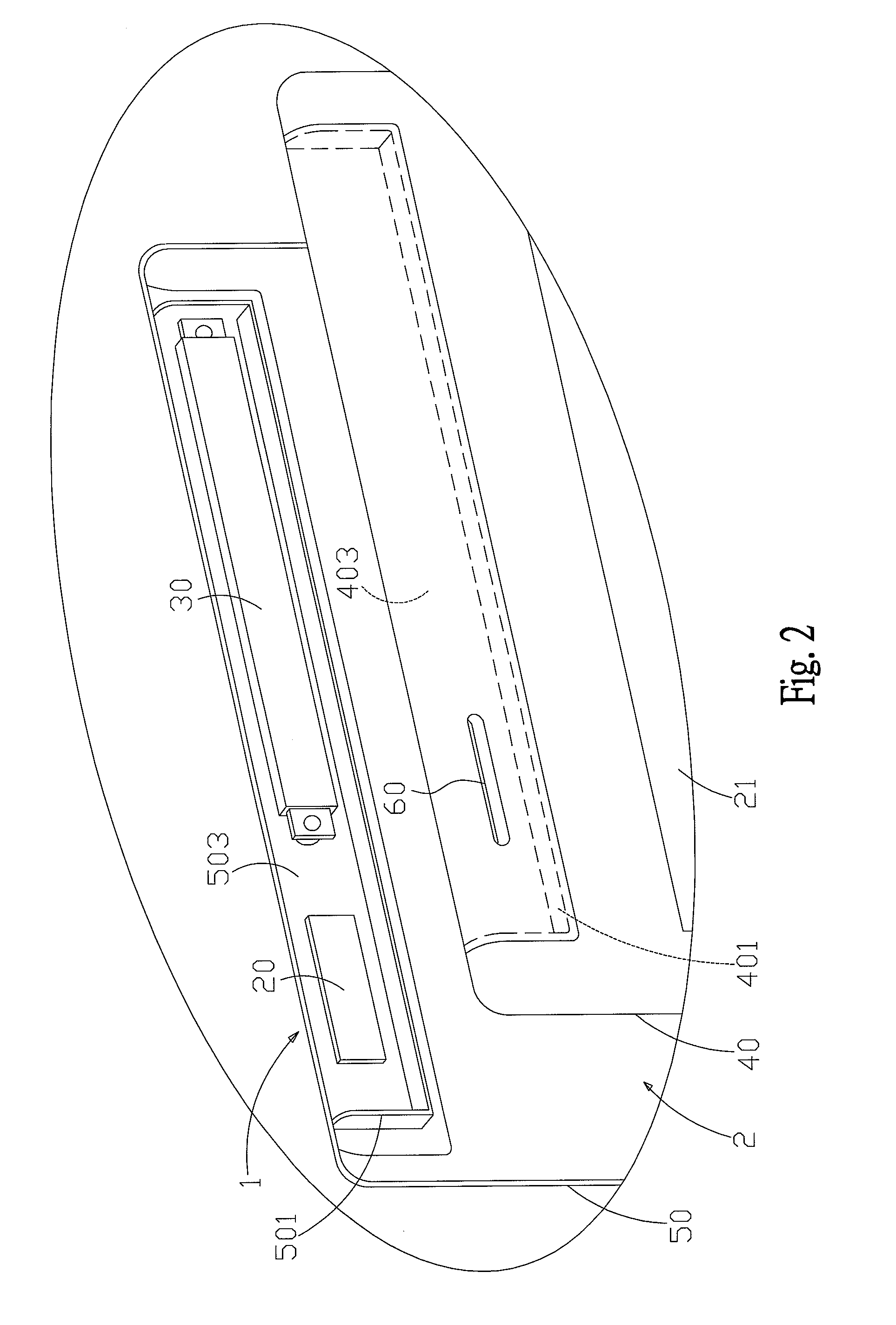
[0014]FIG. 1 shows a structural schematic diagram of the sound box structure according to the present disclosure. As shown in the figure, the present disclosure provides a sound box structure for an electronic apparatus. The sound box structure 1 is disposed in an electronic apparatus 2. The electronic apparatus 2 according to the present embodiment can be portable electronic apparatuses such as notebook computers, tablet computers, personal digital assistants, and smart phones. The sound box structure 1 comprises a resonating cavity 10, a loudspeaker 20, and at least an electronic device 30. The loudspeaker 20 and the electronic device 30 are disposed in the resonating cavity 10. The electronic device 30 can be a wireless transmission module, an image extraction module, a touch module, or a sensing module. The electronic device 30 according to the present embodiment is a wireless transmission module, such as an antenna, a wireless network communication module, a GSM (Global System ...

second embodiment

[0018]FIG. 3B shows a cross-sectional view of a second embodiment according to the present disclosure. As shown in the figure, the first sidewall 401 (or the second sidewall 501) is a general convex rib; the second sidewall 501 (or the first sidewall 401) is a soft material. The second sidewall 501 corresponds to the first sidewall 401. The first housing 40 is assembled with the second housing 50. The first sidewall 401 pushes against the second sidewall 501. Because the second sidewall 501 is a soft material, it can mate tightly with the first sidewall 401 for forming the resonating cavity 10.

third embodiment

[0019]FIG. 4 shows a structural schematic diagram of the sound box structure according to the present disclosure. As shown in the figure, the difference between the present embodiment and the previous one is that the present embodiment further comprises a reinforcing space 70, which extends on at least one side of the resonating cavity 10. Thereby, the output audio quality of the sound box structure 1 is enhanced, and thus improving the multimedia effects of the electronic apparatus 2.

[0020]To sum up, the present disclosure relates to a sound box structure for an electronic apparatus. The sound box structure is disposed in an electronic apparatus and comprises a resonating cavity, a loudspeaker, and at least an electronic device. The loudspeaker and the electronic device are disposed in the resonating cavity. The present disclosure mainly combines the sound box structure disposed originally in the electronic apparatus with the accommodating space of other electronic devices for expa...


PUM


Abstract

The present disclosure relates to a sound box structure for an electronic apparatus. The sound box structure is disposed in an electronic apparatus and comprises a resonating cavity, a loudspeaker, and at least an electronic device. The loudspeaker and the electronic device are disposed in the resonating cavity. The present disclosure mainly combines the sound box structure disposed originally in the electronic apparatus with the accommodating space of other electronic devices for expanding the resonating space of the sound box structure for the electronic apparatus. Consequently, the output audio quality of the sound box structure for the electron apparatus can be improved, and hence enhancing the multimedia effects of the electronic apparatus.

Description

FIELD OF THE DISCLOSURE[0001]The present disclosure relates generally to a sound box structure, and particularly to a sound box structure used in an electronic apparatus.BACKGROUND OF THE DISCLOSURE[0002]Modern electronic technologies are developed so rapidly that various electronic apparatuses prevail in the society. Not only the computation capabilities are getting stronger but also the processing speed grows exponentially. Electronic apparatuses such as notebook computers, mobile phones, multimedia players, and personal digital assistants have become people's indispensable parts in learning, entertaining, and working; they are compact, convenient for carrying, and increasingly stronger functionality attract market and customers' attention and hence are adopted by the general public. In addition to enhanced operating performance, electronic apparatuses are further designed thinly with multimedia functions. Thereby, most of them will have a suitable tiny loudspeaker as the audio ou...

Claims


Application Information

Patent Timeline
Patent Type & Authority Applications(United States)
IPC IPC(8): H04R1/20H04R1/02
CPCH04R1/2811H04R2420/07H04R2499/11
Inventor SUN, TSAI-YUN
Owner WISTRON CORP
Learn More