
Use of electro-static mask to apply layers to an electro-active optical element

an electro-static mask and optical element technology, applied in the direction of instruments, coatings, spectacles/goggles, etc., can solve the problems of requiring additional processing steps, etc., and achieve the effect of reducing or eliminating the use of adhesive materials and affecting the appearance or performance of the electro-active lens

Inactive Publication Date: 2012-11-29
MITSUI CHEM INC
View PDF5 Cites 4 Cited by
  • Summary
  • Abstract
  • Description
  • Claims
  • Application Information

AI Technical Summary

Benefits of technology

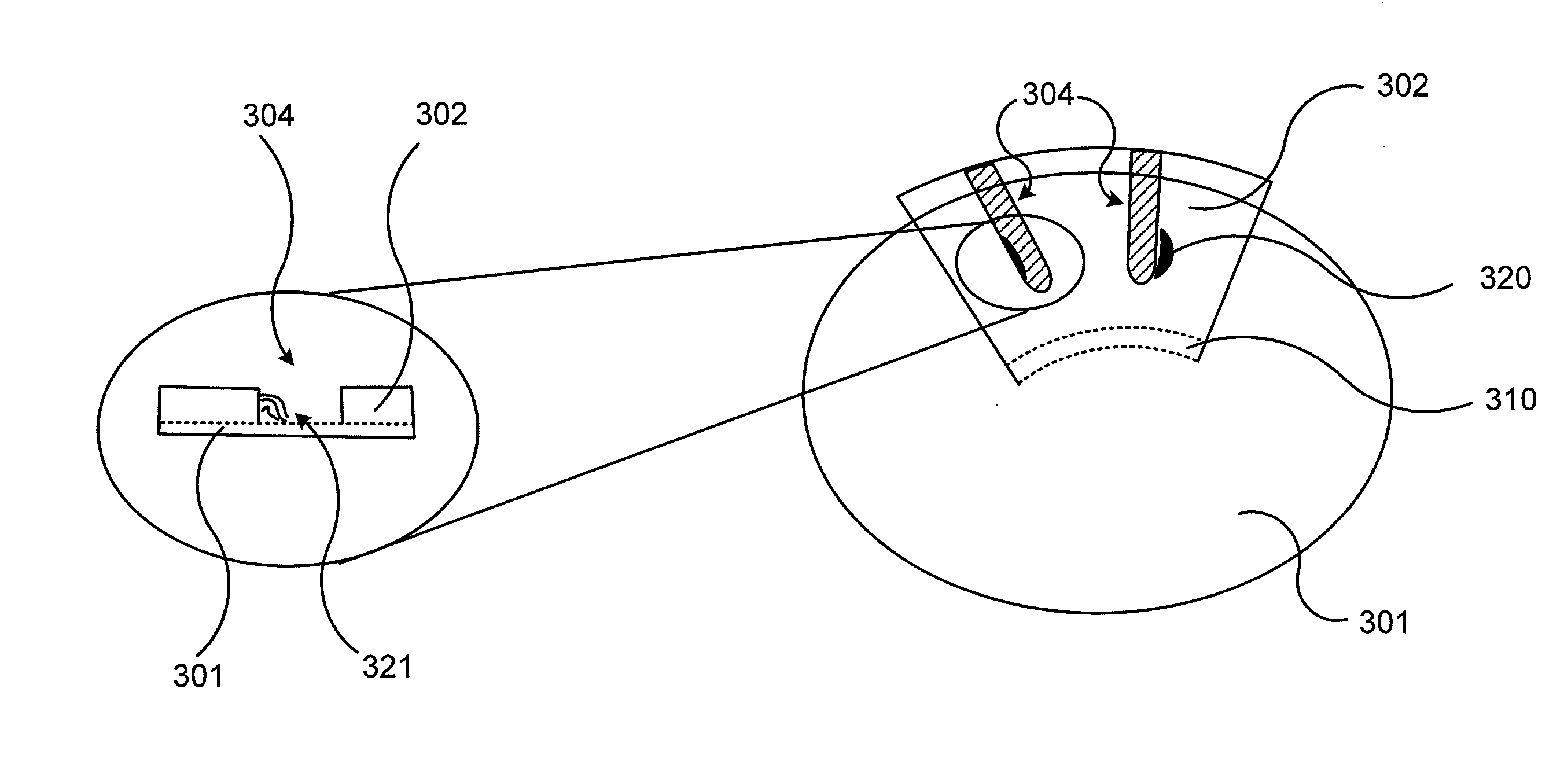
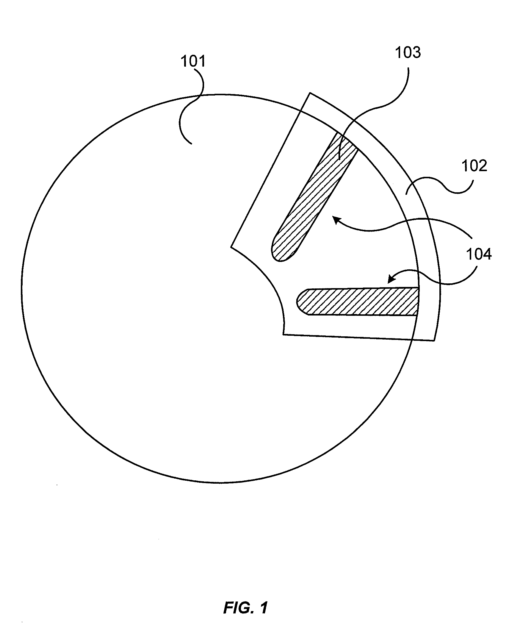
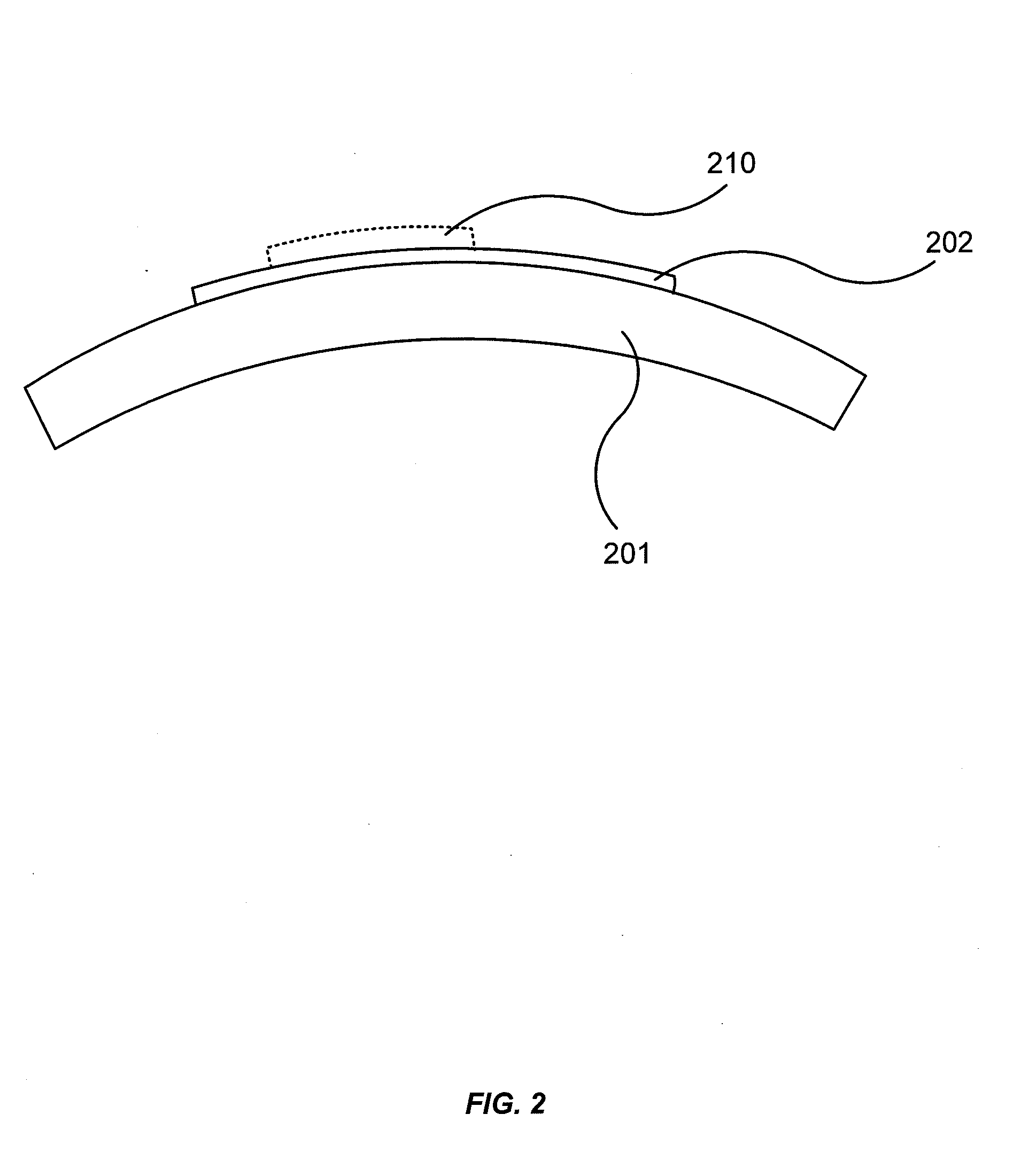
The patent describes a method for manufacturing an electro-active lens by depositing layers of material over a substrate using a mask. The mask is held in place by an electro-static force created between the mask and the substrate. The mask is made of a flexible material and can be aligned based on an optical feature on the substrate. The method does not require an adhesive layer between the substrate and the mask, which can contaminate the layers and affect their performance. The use of an electro-static material eliminates the need for an adhesive and reduces the complexity of the process. The method can be used to manufacture electro-active lenses with improved efficiency and performance.

Problems solved by technology

In some embodiments, this may reduce or eliminate the use of adhesive materials or similar materials that are typically used to hold the mask in place, which can contaminate one or more of the electro-active layers of the device, require additional processing steps to remove such layers, and / or otherwise affect the appearance or performance of the electro-active lens.

Method used


Image

  • Use of electro-static mask to apply layers to an electro-active optical element
  • Use of electro-static mask to apply layers to an electro-active optical element
  • Use of electro-static mask to apply layers to an electro-active optical element

Examples


Embodiment Construction

[0025]Some terms that are used herein are described in further detail as follows:

[0026]As used herein, the term “alignment layer” may refer to a layer of material that controls the alignment of liquid crystals in the absence of an external field and often adheres to the surface of a substrate (such as an electrode, a lens, lens blank, lens wafer, etc.).

[0027]As used herein, the term “comprising” is not intended to be limiting, but may be a transitional term synonymous with “including,”“containing,” or “characterized by.” The term “comprising” may thereby be inclusive or open-ended and does not exclude additional, unrecited elements or method steps when used in a claim or to describe an embodiment. For instance, in describing a method, “comprising” indicates that the claim is open-ended and allows for additional steps. In describing a device, “comprising” may mean that a named element(s) may be essential for an embodiment, but other elements may be added and still form a construct wi...


PUM


Abstract

A method for manufacturing an electro-active lens may be provided. The method may comprise the steps of providing a substrate having a first surface; disposing a mask over at least a portion of the first surface of the substrate, where the mask comprises an electro-static plastic material and where the mask has at least one opening; and depositing a layer of material through the at least one opening of the mask.

Description

CROSS-REFERENCES TO RELATED APPLICATIONS[0001]This application claims benefit under 35 U.S.C. §119(e) of U.S. provisional patent application No. 61 / 489,909, filed on May 25, 2011, the entire disclosure of which is incorporated herein by reference for all purposes.BACKGROUND OF THE INVENTION[0002]Electronic (i.e. “electro-active”) lenses that are configured to have their optical properties altered by way of passing an electrical current or potential across a layer of material (such as a liquid crystal layer) disposed between two electrodes are generally known. In the case of a pixilated electronic lens the electrodes may be individually addressable and thus multiple electrodes may be required, but in the case of a surface relief diffractive optic, only two electrodes are generally needed: one disposed on the top substrate and one disposed on the bottom substrate. One or more of the layers of the electro-active lens may be deposited through a mask, which is typically coupled to one of...

Claims


Application Information

Patent Timeline
Patent Type & Authority Applications(United States)
IPC IPC(8): B05D1/32
CPCG02C7/083
Inventor HALL, ROBERT S.TRAJKOVSKA, ANITA
Owner MITSUI CHEM INC
Learn More