Skirt for Photovoltaic Arrays

a photovoltaic array and solar panel technology, applied in the direction of solar heat collector mounting/support, solar heat collector safety, lighting and heating apparatus, etc., can solve the problems of flammable materials, fire safety hazards, organic debris,

Active Publication Date: 2012-11-29
TESLA INC
View PDF8 Cites 82 Cited by
  • Summary
  • Abstract
  • Description
  • Claims
  • Application Information

AI Technical Summary

Benefits of technology

[0011]The following embodiments and aspects thereof are described and illustrated in conjunction with systems, apparatus, tools, and methods which are meant to be exemplary and illustrative, not limiting in scope. In various embodiments, one or more of the above-described problems have been reduced or eliminated, while other embodiments are directed to other advantages or improvements.

Problems solved by technology

The presence of an air gap opening on the sides of a PV array, as well as between PV module frames on the top surface, may result in organic debris (such as leaves and sticks) entering and becoming trapped under the array, which may in turn result in a fire safety hazard.
Rodents / birds / insects and other pests may also enter through these opening and contribute to the accumulation of flammable material through the building of nests, as well as potentially damaging electrical wires contained beneath the array.
Regardless of debris, flames from a building fire may enter the air gap beneath an array and compromise the fire safety rating of the roofing material located underneath by trapping hot air, gases, vapor or plasma that typically dissipate if not otherwise confined.
However, these systems suffer from a number of drawbacks.
Prior skirt systems do not appear to provide adequate structural support.
Therefore, on a steep roof the weight of the PV array plus other loads, such as snow or an installation technician may not be properly supported, especially in the 4-corners region.
Prior skirt systems also do not appear to provide a means to accomplish the desired blocking the spread of flames or providing visual aesthetics by blocking a view of the area beneath a PV module or array, while allowing for enough airflow to adequately reduce the temperature of the PV array.
Prior skirt systems do not appear to provide skirts that adequately block animals and debris since such systems do not typically cover enough of the gap beneath a PV array to be sufficient.
For example, roof surfaces are rarely flat yet prior systems provide only a rigid, flat screen, thereby resulting in gaps between the screen and the roof surface.
Prior systems also do not provide height adjustability so that a screen may be moved closer to or in contact with a roof surface.
Prior skirt systems require numerous parts which increase the cost of installation for the PV array.
Prior skirt systems also appear not to provide a simple method, apparatus or system for creating a ground bond between a skirt and a PV array.
The parts and labor associated with running a separate ground wire to a skirt is a significant cost.
Furthermore, many on-roof grounding systems have suffered problems in the field due to corrosion, which exacerbates the problems of post-installation addition of grounding wires.
Other limitations of the related art will become apparent to those of skill in the art upon a reading of the specification and a study of the figures.

Method used


Image

  • Skirt for Photovoltaic Arrays
  • Skirt for Photovoltaic Arrays
  • Skirt for Photovoltaic Arrays

Examples


embodiment 260

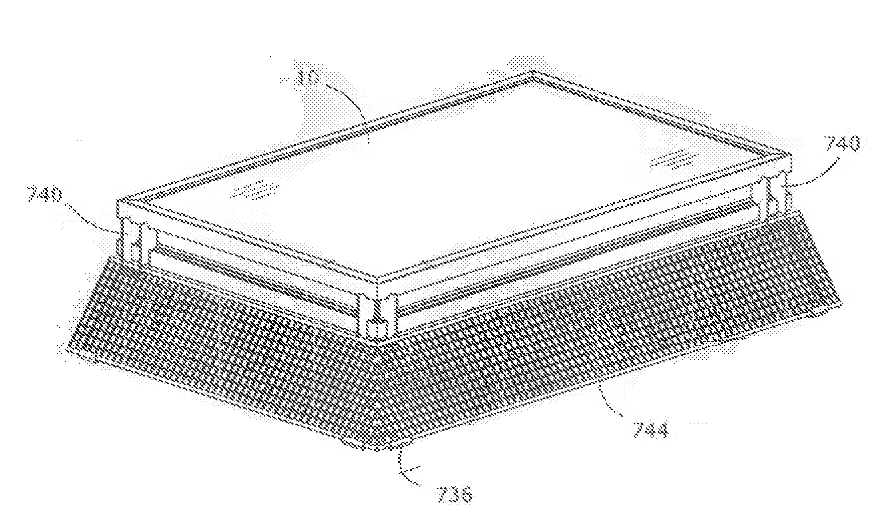
[0074]FIGS. 60-63 show skirt embodiment 260 comprising louvers 79 located along the top of portion 260A of skirt 260. A separate flexible screen material 370 may be attached to the bottom of the skirt using common fasteners.

[0075]In embodiments skirt and screen elements disclosed above may be constructed of flexible materials that may conform to surface variations on the roof, thus providing an effective barrier.

embodiment 264

[0076]FIG. 64A shows a skirt embodiment 264 comprising a scalloped lower portion that conforms to a shape of a curved tile roof 305. FIG. 64B is a detail view of area in circle of FIG. 64A.

[0077]FIG. 65 disclose the manner in which the wedging fit of an anti-rotation component 11 may prevent interlock 6 from disengaging from within a module frame groove 3 due to rotation caused by downward module deflection created by heavy loading due to imposed forces from snow, ice or wind. This disengagement may once again be prevented by forcing a surface 13 of the anti-rotation component 11 in direct contact with a surface of a module frame 15.

[0078]FIG. 66 shows an accessory component assembly 600 that may be used to mount electrical boxes 500 of various types to groove 3. As FIG. 66 shows, anti-rotation components 11 may also be inserted into apertures 412 located within the accessory component assembly 600 in order to prevent rotational movement of the assembly after it has been installed.

[...


PUM

PropertyMeasurementUnit
angleaaaaaaaaaa
perimeteraaaaaaaaaa
flexibleaaaaaaaaaa

Abstract

A skirt for photovoltaic arrays provides a screen portion, a groove portion, and a separate coupling adapted to couple the skirt to the skirt of an adjacent photovoltaic array and to a photovoltaic module. Another embodiment provides a screen portion comprising an angled louver and is adapted to partially obscure an area substantially beneath a PV module in a PV array. A further embodiment provides an edge blocking skirt for a PV array comprising a screen portion adapted for mounting a bottom of the screen portion substantially close to a roof.

Description

CROSS REFERENCES[0001]The present application claims the benefit of the filing date of U.S. Provisional Patent Application Ser. No. 61 / 421,626, filed Dec. 9, 2010; and U.S. Provisional Patent Application Ser. No. 61 / 421,629, filed Dec. 9, 2010. The foregoing applications are incorporated by reference in their entirety as if fully set forth herein.BACKGROUND[0002]It is common in the art to install photovoltaic (PV) arrays at an offset height above a support surface, such as a roof surface (of shingle, tile, roof membrane or the like). Such a mounting arrangement may provide an air gap beneath the PV array. The offset height distance may provide space for wire management and to allow for PV arrays or PV modules to be mounted above vent pipes and other common roof obstructions. Gaps between PV module frames on the top surface of a PV array may be required to allow space for mounting hardware as well as to allow for dimensional tolerance variation, thermal expansion and the like.[0003]T...

Claims


Application Information

Patent Timeline
Patent Type & Authority Applications(United States)
IPC IPC(8): H01L31/0203B32B3/06
CPCF24J2/045Y10T428/24008F24J2/5211F24J2/5245F24J2/526F24J2002/4665F24J2002/5226F24J2002/5294Y02B10/20Y02E10/47F24J2/4609Y02E10/50Y02B10/12H02S20/00H02S30/10H02S20/23F24J2/465F24S2025/014F24S20/67F24S40/10F24S80/70F24S25/20F24S25/61F24S25/632F24S25/65F24S2025/6004F24S2025/807F24S2025/021Y02B10/10
Inventor WEST, JOHN RAYMONDHUDSON, TYRUS HAWKESJOHANSEN, EMILCAPSUTO, IANMEDCROFT, CHADATCHLEY, BRIANCOLEMAN, NATE
Owner TESLA INC
Why Eureka
Try Eureka