Cooling device for a battery module

a battery module and cooling device technology, applied in the direction of sustainable manufacturing/processing, climate sustainability, final product manufacturing, etc., can solve the problems of pressing force on the cooler and stress on the cooler

Active Publication Date: 2012-11-29
BEHR GMBH & CO KG
View PDF2 Cites 17 Cited by
  • Summary
  • Abstract
  • Description
  • Claims
  • Application Information

AI Technical Summary

Benefits of technology

[0019]Alternatively, the tensioning device can be connected via a joint with the spring element. This can improve, for example, the tensioning behavior.

Problems solved by technology

In such a case, there can be the problem during installation that the pressing force on the cooler must occur by means of the installation of the cells or modules, because the springs are no longer accessible after installation.
Because not all cells or modules can be installed simultaneously, however, the problem arises during installation that the cooler is stressed by the spring forces in the area where the cells or modules have still not been installed.
The total pressing force of the springs acts here on the cooler itself and can damage it.

Method used


Image

  • Cooling device for a battery module
  • Cooling device for a battery module
  • Cooling device for a battery module

Examples


Embodiment Construction

[0048]In the following description of the exemplary embodiments of the present invention, the same or similar reference characters are used for the elements with a similar action and shown in the different drawings, whereby a repeated description of these elements is omitted.

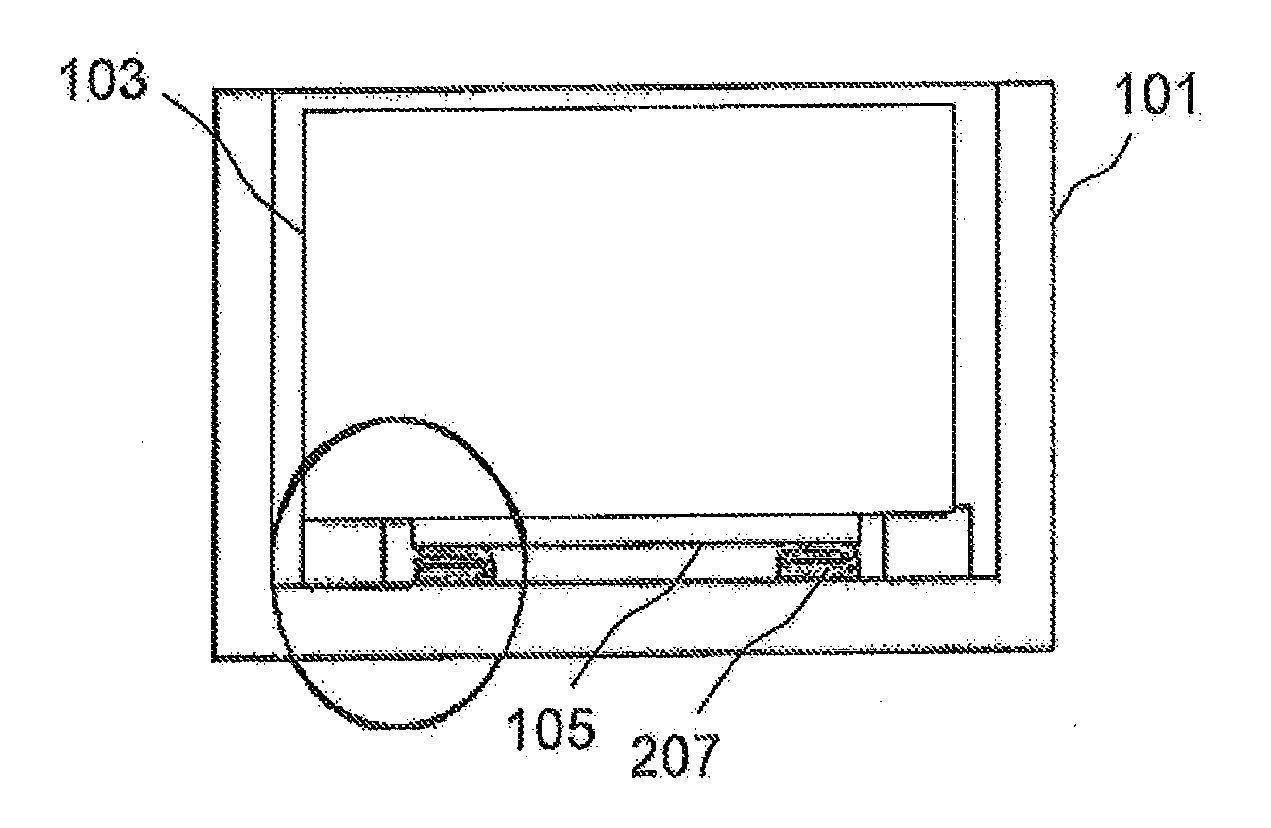
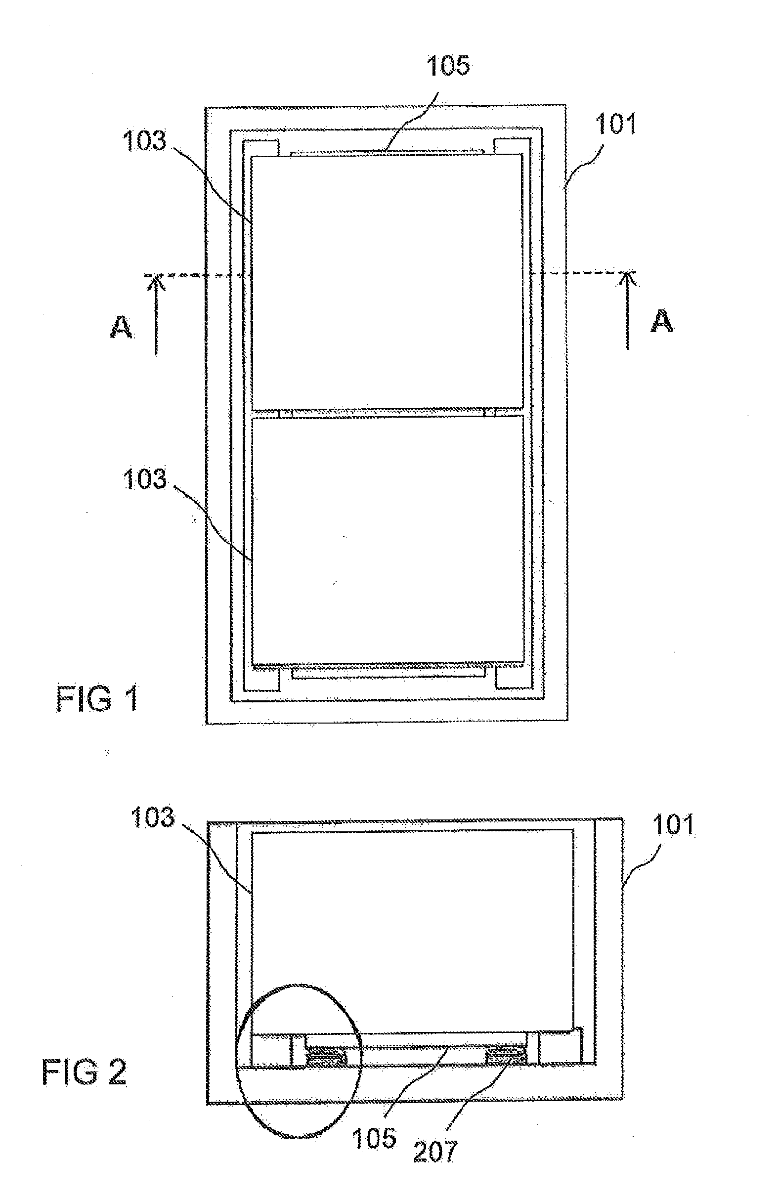
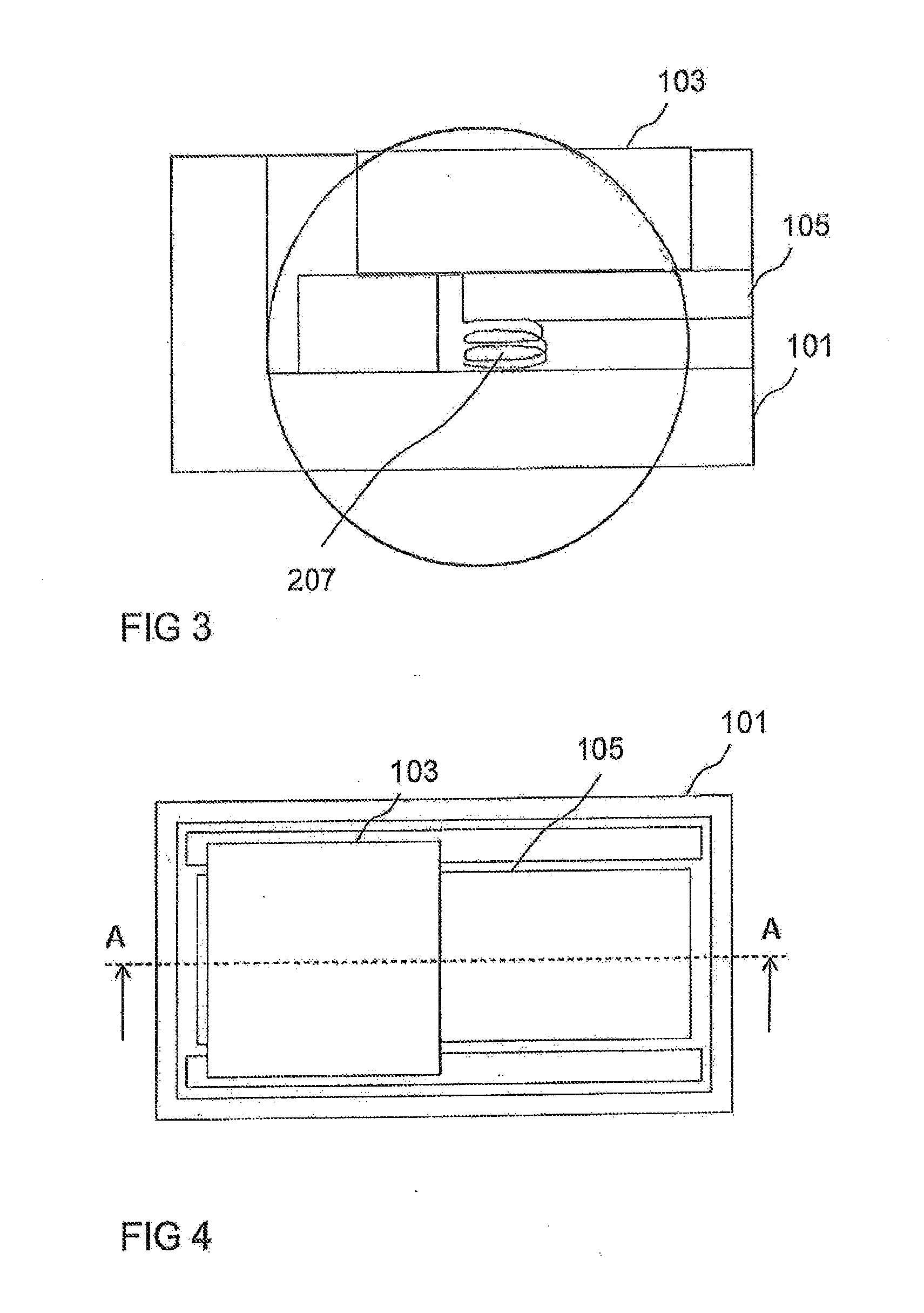
[0049]FIG. 1 shows a plan view of a battery device. The battery device has a battery housing 101 and two battery modules 103, which are arranged next to one another in housing 101. A cooling element 105 extends below battery modules 103 within battery housing 101. A section line A-A is shown as well.

[0050]FIG. 2 shows a sectional view through the battery device shown in FIG. 1 along section line A-A. Shown is battery housing 101 with a bottom element and two side elements, as well as battery module 103, which is disposed in housing 101 on stops. Cooling element 105 lies against a bottom side of battery module 103. Cooling element 105 is pressed by means of springs 207 against battery module 103. Thus, a spring 2...


PUM

PropertyMeasurementUnit
pressing forceaaaaaaaaaa
spring tensionaaaaaaaaaa
areaaaaaaaaaaa

Abstract

A cooling device for a battery module is provided that includes a cooling element having at least one through hole extending from a first side of the cooling element facing the battery module to an opposite second side of the cooling element, at least one spring element disposed on the second side of the cooling element, in order to exert a contact force on the second side of the cooling element in a tensioned condition, and at least one clamping device coupled to the spring element and extending through the through hole, wherein a contact region of the clamping device extends beyond the second side of the cooling element when the spring element is in a relaxed condition.

Description

[0001]This nonprovisional application is a continuation of International Application No. PCT / EP2010 / 068861, which was filed on Dec. 3, 2010, and which claims priority to German Patent Application No. DE 10 2009 058 070.0, which was filed in Germany on Dec. 14, 2009, and which are both herein incorporated by reference.BACKGROUND OF THE INVENTION[0002]1. Field of the Invention[0003]The present invention relates to a cooling device for a battery module and to a battery device.[0004]2. Description of the Background Art[0005]High-performance energy storage devices such as, for example, Li-ion or NiMH accumulators or supercaps are used in modern hybrid electric and electric vehicles (HEV / EV) vehicles. Heating occurs in these during rapid charging and discharging due to resistances within and outside the cells. Temperatures above 50° C. damage the energy storage devices permanently. To assure the function of the energy storage devices, they must be actively cooled. For this purpose, the en...

Claims


Application Information

Patent Timeline
Patent Type & Authority Applications(United States)
IPC IPC(8): H01M10/50
CPCH01M10/0481H01M10/5053H01M10/5016H01M10/5004H01M10/613H01M10/625H01M10/6554Y02E60/10Y02P70/50
Inventor HIRSCH, STEFAN
Owner BEHR GMBH & CO KG
Why Eureka
Try Eureka