
Green Data Center and the Method for Achieving Power Usage Efficiency less than 1

a technology of data center and power consumption efficiency, applied in the direction of position/direction control, liquid/fluent solid measurement, resources, etc., can solve the problems of large power cost and serious burden on the servers or data centers of these websites, and achieve the effect of reducing the needs of utility power and reducing the usage and cost of utility power

Inactive Publication Date: 2012-11-29
GCCA
View PDF0 Cites 6 Cited by
  • Summary
  • Abstract
  • Description
  • Claims
  • Application Information

AI Technical Summary

Benefits of technology

[0009]One purpose of the present invention is to lower PUE of the data center, so as to reduce the usage of the utility power and to further decrease the energy consumption, thereby implementing the effect of energy-saving and carbon-reducing.
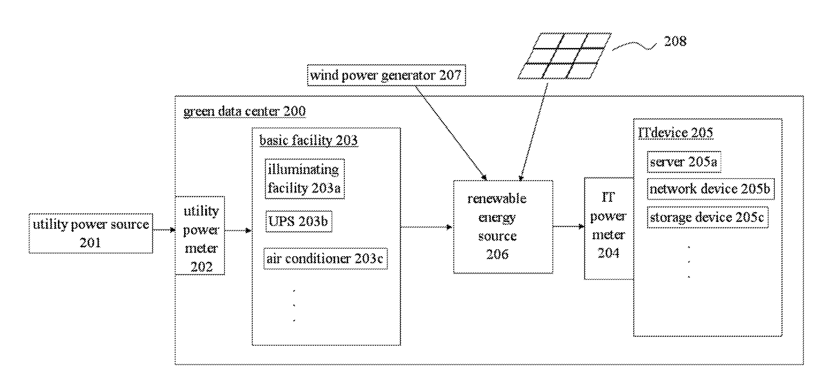
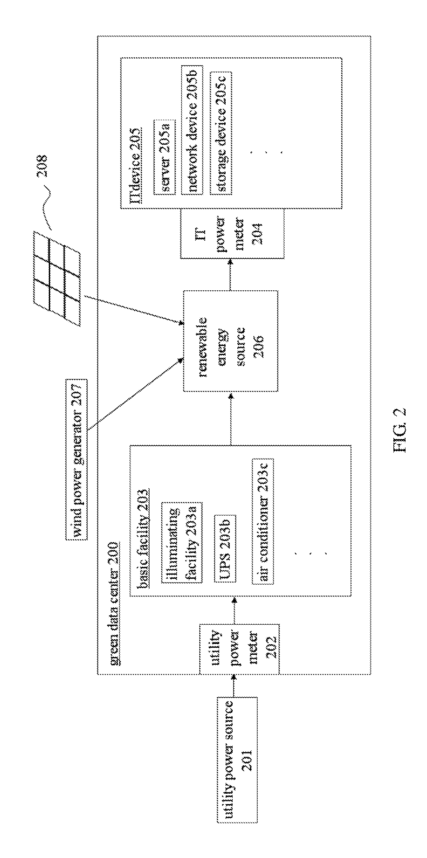
[0014]The data center of the present invention further comprises a renewable energy source electrically connected to the wind power generator and / or the solar energy panel, and the renewable energy can be transmitted into the data center for providing extra power to the IT device, thereby reducing needs of the utility power. As a result, total power received by the IT device may be greater than the utility power provided by the utility power source, whereby making PUE less than 1. Therefore, the usage and cost of the utility power can be reduced effectively if enough renewable energy is provided, so that the effect of energy-saving and carbon-reducing can be achieved.

Problems solved by technology

However, it may seriously burden the servers or data centers of these websites.
For those companies of websites, the power cost is quite considerable.
However, the power and the energy has become more and more precious nowadays, and hence, to promote the energy efficiency or to reduce the energy consumption is still urgent for human beings.

Method used


Image

  • Green Data Center and the Method for Achieving Power Usage Efficiency less than 1
  • Green Data Center and the Method for Achieving Power Usage Efficiency less than 1
  • Green Data Center and the Method for Achieving Power Usage Efficiency less than 1

Examples


Embodiment Construction

[0020]Some sample embodiments of the invention will now be described in greater detail. Nevertheless, it should be recognized that the present invention can be practiced in a wide range of other embodiments besides those explicitly described, and the scope of the present invention is expressly not limited expect as specified in the accompanying claims.

[0021]Referred to FIG. 2, which depicts the preferred embodiment of the green data center disclosed by the present invention, the green data center 200 includes a utility power source 201, a utility power meter 202, a basic facility 203, a renewable energy source 206, an IT power meter 204, and an IT device 205. In this embodiment, the facility power source 201, which may be a power supply of the power company, is electrically connected to the basic facility 203 via the utility power meter 202, so as to provide the utility power to the data center 200. Part of the utility power can be consumed by the basic facility 203 for operation. I...


PUM


Abstract

A green data center is provided, which comprises: a utility power source for providing utility power; a facility electrically connected to the utility power source; a renewable energy provider electrically connected to the facility for providing renewable energy; an IT equipment electrically connected to the renewable energy provider; wherein the total power received by the IT equipment is not less to the utility power provided by the utility power source, so that the PUE (Power Usage Efficiency) can be less than one, thereby achieving the effect of carbon-reducing and energy-saving.

Description

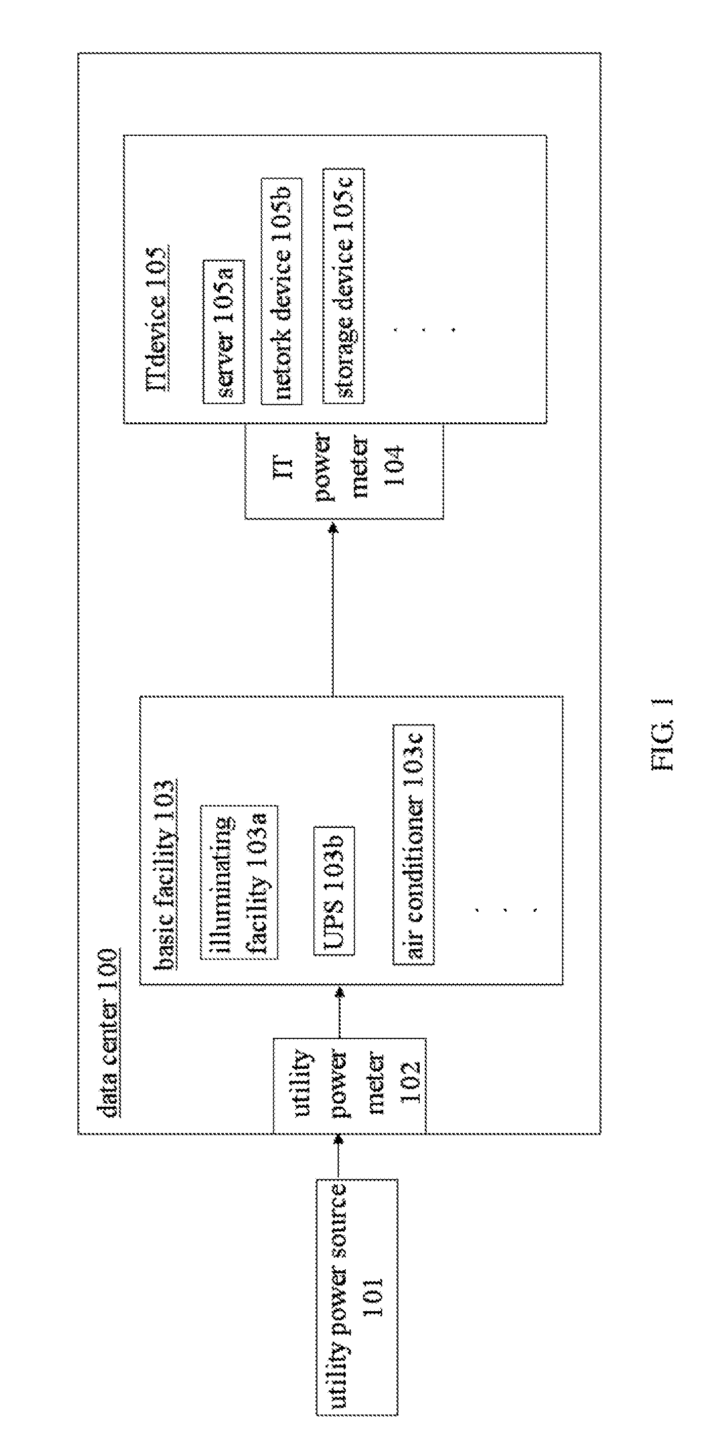
FIELD OF THE INVENTION[0001]The present invention generally relates to a green data center, in particular, to a green data center and the operating method capable of achieving PUE (power usage efficiency) less than 1.DESCRIPTION OF THE PRIOR ART[0002]In pace with the development of technology, the flourish of the network recently breeds many websites to attract members up to millions or even more, such as: Google, Facebook, Yahoo, Youtube, Twitter, Myspace, and so on. These well-known websites, benefited from the trend of the network, are browsed by members from the whole world in every single minute. However, it may seriously burden the servers or data centers of these websites. Therefore, a great amount of power must be required for the data center, so as to prevent the failure of the website.[0003]Generally speaking, a conventional data center comprises basic facilities and IT devices, wherein the basic facilities, including the illuminating facility, the UPS, the air conditioner...

Claims


Application Information

Patent Timeline
Patent Type & Authority Applications(United States)
IPC IPC(8): G06F1/26
CPCG06Q50/06Y02E40/76Y04S10/545G06Q10/063Y02E40/70Y04S10/50
Inventor SZU, OLIVERTSENG, STONE
Owner GCCA
Learn More