Efficient refrigerating system and control method

A refrigeration system, high-efficiency technology, applied in refrigerators, refrigeration components, refrigeration and liquefaction, etc., can solve the problems of small cooling capacity, poor heat transfer capacity of evaporator, delay of control system, etc., to achieve heat transfer capacity improvement, evaporation The effect of increasing temperature and reducing PUE

Pending Publication Date: 2022-06-21
SUZHOU LANGCHAO INTELLIGENT TECH CO LTD
View PDF0 Cites 0 Cited by
  • Summary
  • Abstract
  • Description
  • Claims
  • Application Information

AI Technical Summary

Problems solved by technology

[0004] The problem existing in the existing refrigeration system is that in order to ensure that the inlet of the compressor absorbs pure gaseous refrigerant and avoid liquid refrigerant entering the compressor and causing liquid shock damage to the compressor, it is necessary to ensure that the gaseous refrigerant at the outlet of the evaporator has a large excess. Heat (SH), usually SH is set to 12 ~ 15 °, some manufacturers even set it to 20 °, at this time the evaporator is divided into a gas-liquid two-phase heat exchange area and an overheating area, in which the gas-liquid two-phase heat exchange area is cooled by refrigeration The phase change of the agent has a huge cooling capacity, while the superheated area is a gaseous single-phase heat exchange, and the cooling capacity is very small
However, due to the uneven distribution of liquid in the flow path of the evaporator and the delay of the control system, even with a suction separator, it is necessary to set a larger preset value of the superheat, which will still cause the heat transfer capacity of the evaporator to deteriorate

Method used


Image

  • Efficient refrigerating system and control method
  • Efficient refrigerating system and control method
  • Efficient refrigerating system and control method

Examples


Embodiment 1

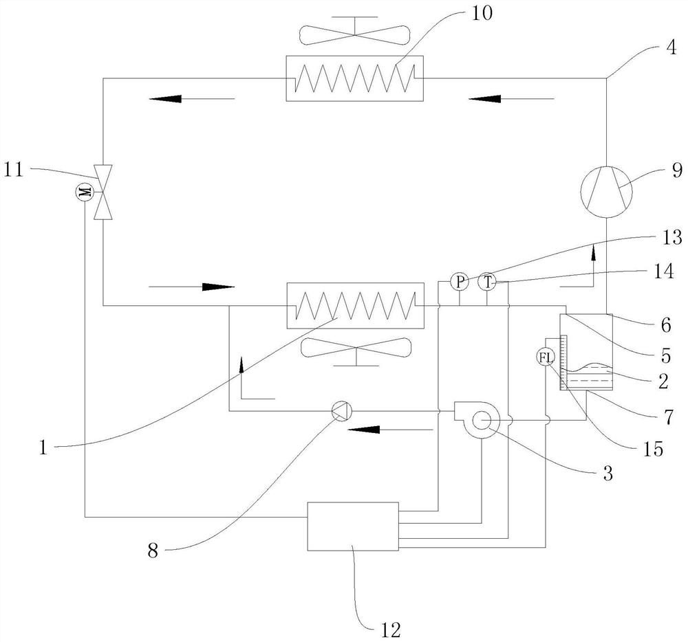
[0048] provide an efficient cooling system such as figure 2 As shown, it includes an evaporator 1 , a liquid separation tank 2 communicated with the evaporator 1 , a fluorine pump 3 communicated with the liquid separation tank 2 and a first pipeline 4 . The outlet end of the evaporator 1 is communicated with the liquid separation tank 2, the inlet of the fluorine pump 3 is communicated with the liquid separation tank 2, the outlet end is communicated with the inlet end of the evaporator 1, and the fluorine pump 3 is used to remove the refrigerant in the liquid separation tank 2. Suck it out and enter the port evaporator 1 through the inlet port. Wherein, the liquid separation tank 2 is provided with an air inlet 5, an air outlet 6 and a liquid outlet 7, the liquid separation tank 2 is cylindrical, and the air inlet 5 and the air outlet 6 are respectively arranged on the top of the liquid separation tank 2. The liquid port 7 is arranged at the bottom of the liquid separation ...

Embodiment 2

[0054] Corresponding to the above embodiments, the present application provides a control method based on the above-mentioned high-efficiency refrigeration system, the method comprising:

[0055] Step S1: Receive the pressure and temperature when the gas is output to the evaporator 1, and obtain the real-time superheat SH.

[0056] Among them, SH is the suction superheat degree, and its value is the difference between the temperature when the refrigerant is output to the evaporator 1 (that is, the suction temperature T when the gas enters the compressor 9) and the saturation temperature corresponding to the suction pressure P, its physical meaning Indicates the degree to which the gas temperature exceeds the saturated gas temperature under this pressure; its physical meaning determines that the suction superheat degree of the compressor 9 is greater than or equal to 0.

[0057] Specifically, a pressure sensor 13 and a temperature sensor 14 are installed at the outlet of the ev...

Embodiment 3

[0079] In a present embodiment, a computer-readable storage medium is provided, on which a computer program is stored, and when the computer program is executed by a processor, the following steps are implemented:

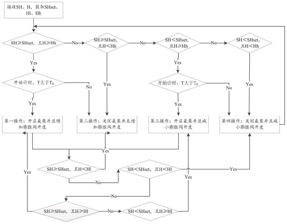
[0080] Receive the pressure and temperature when the gas is output to the evaporator 1, and obtain the real-time superheat SH;

[0081] Receive the liquid level in the liquid separation tank 2 to obtain the real-time liquid level H;

[0082] Comparing the real-time superheat degree with the preset superheat degree SHset, and comparing the real-time liquid level H with the preset high liquid level Hh or the preset low liquid level H1, to obtain a comparison result;

[0083] According to the comparison result, the states of the fluorine pump 3 and the electronic expansion valve 11 are regulated.

[0084] Specifically, when the staff sets the system to start running, it enters the first control mode, and performs the corresponding operation through the comparison bet...


PUM


Abstract

The invention discloses an efficient refrigeration system and a control method, and relates to the technical field of refrigeration. Comprising an evaporator, a liquid separation tank connected with the outlet end of the evaporator, a fluorine pump connected with the liquid separation tank and a first pipeline, the liquid separation tank is provided with an air inlet, an air outlet and a liquid outlet, the air inlet is communicated with the outlet of the evaporator, the outlet of the fluorine pump is communicated with the inlet of the evaporator, and the liquid outlet is communicated with the liquid outlet. The evaporator, the liquid separation tank, the fluorine pump and the first pipeline form a first refrigeration circulation loop. And the relation between the real-time superheat degree and the preset superheat degree is compared, the relation between the real-time liquid level and the first preset liquid level or the second preset liquid level is compared, a comparison result is obtained, the working state of the fluorine pump and the working state of the electronic expansion valve are regulated and controlled through the controller, and efficient refrigeration of the refrigeration system is achieved.

Description

technical field [0001] The invention relates to the technical field of refrigeration, in particular to a high-efficiency refrigeration system and a control method. Background technique [0002] A data center is a place that provides a safe and reliable operating environment for the centralized placement of electronic information equipment. With the vigorous development of IT technologies such as edge computing, artificial intelligence, big data, Internet of Everything (IoT), and cloud technology, the requirements for data processing, computing power, and data transmission capabilities are getting higher and higher; In 2018, the demand for data centers from various industries such as network operators, Internet companies, governments, and enterprises has exploded, and the construction of data centers has also moved toward a larger scale and higher reliability. The equipment inside the data center emits a huge amount of heat during normal operation. If the heat cannot be brou...

Claims


Application Information

Patent Timeline
Patent Type & Authority Applications(China)
IPC IPC(8): H05K7/20F25B41/40F25B41/20F25B41/34F25B43/00F25B49/02
CPCH05K7/20309H05K7/208F25B41/40F25B41/20F25B41/34F25B43/00F25B49/02
Inventor 郭杰段晓丽郭爽王红卫
Owner SUZHOU LANGCHAO INTELLIGENT TECH CO LTD
Why Eureka
Try Eureka