A cooling system for a data center

A cooling system and data technology, applied in data centers, cooling/ventilation/heating transformation, standard rack/cabinet modification, etc., can solve the problem of increasing the power consumption of circulating fans, large airflow resistance of filters, and poor adaptability and other issues, to achieve significant energy-saving effects, improve system efficiency, and reduce operating energy consumption

Active Publication Date: 2020-05-22
BEIJING BAIDU NETCOM SCI & TECH CO LTD
View PDF11 Cites 0 Cited by
  • Summary
  • Abstract
  • Description
  • Claims
  • Application Information

AI Technical Summary

Problems solved by technology

[0005] The existing air-side energy-saving natural cooling scheme of the data center generally adopts a dedicated air-conditioning unit with fresh air function, such as a direct fresh air unit or an indirect fresh air unit, but it is not well adapted to the building of the computer room, and requires a large amount of storage space in the computer room. Air duct, maintenance area and other spaces
At the same time, the existing air-side energy-saving units all need to install multi-layer filters to remove the pollution of the outdoor environment, and the filter itself produces a large airflow resistance, which increases the power consumption of the circulating fan and weakens the energy-saving effect. Requires more frequent replacement and maintenance, increasing the complexity and cost of personnel operations
In addition, the existing natural cooling units are generally equipped with relatively compact multi-row heat exchangers to meet the heat exchange and humidity control requirements, but the heat exchanger itself will also adversely affect the system wind resistance, and at the same time weaken the energy saving effect

Method used


Image

  • A cooling system for a data center
  • A cooling system for a data center
  • A cooling system for a data center

Examples


Embodiment Construction

[0021] Before discussing the exemplary embodiments in more detail, it should be mentioned that some exemplary embodiments are described as processes or methods depicted as flowcharts. Although the flowcharts describe operations as sequential processing, many of the operations may be performed in parallel, concurrently, or simultaneously. In addition, the order of operations can be rearranged. The process may be terminated when its operations are complete, but may also have additional steps not included in the figure. The processing may correspond to a method, function, procedure, subroutine, subroutine, or the like.

[0022] Specific structural and functional details disclosed herein are representative only and for purposes of describing example embodiments of the present invention. This invention may, however, be embodied in many alternative forms and should not be construed as limited to only the embodiments set forth herein.

[0023] It will be understood that although t...


PUM


Abstract

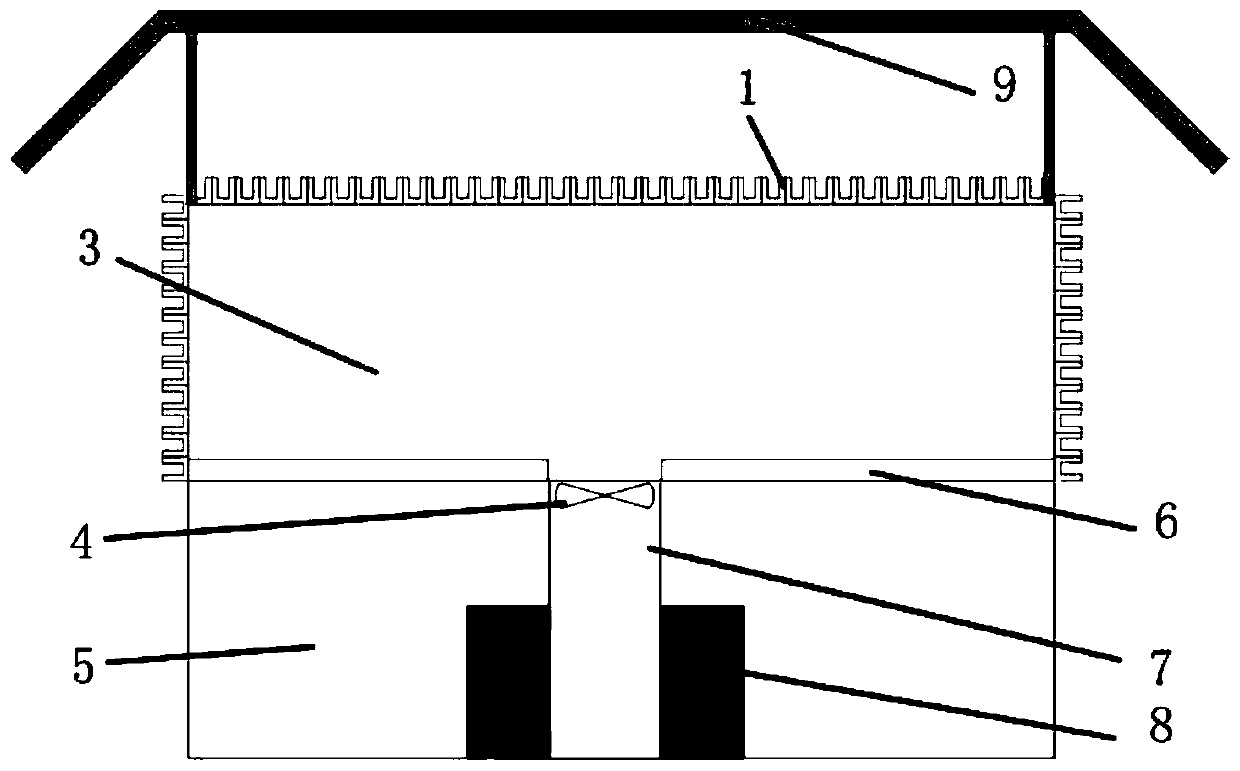
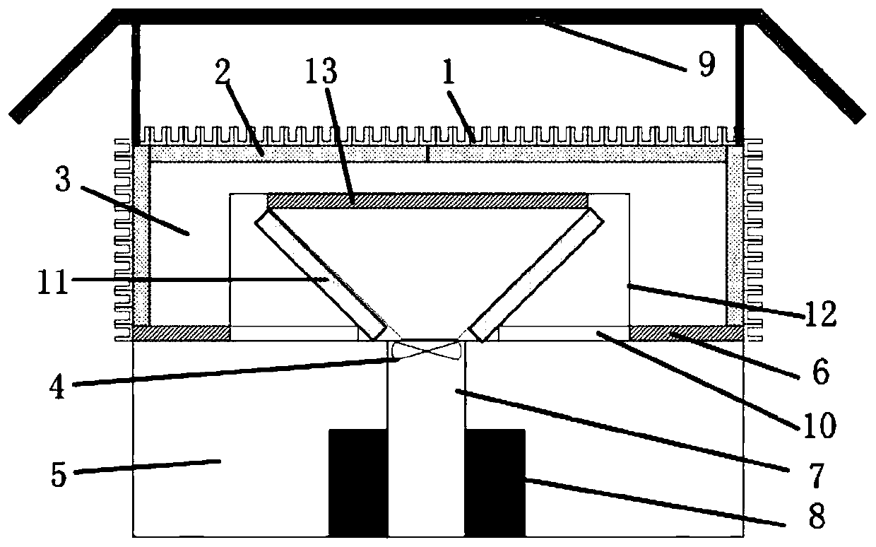
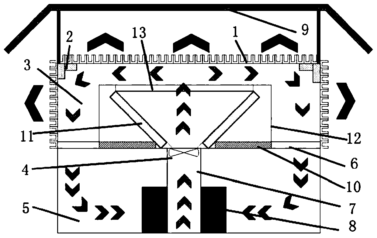
An objective of the present disclosure is to provide a cooling system for a data center. The system includes: a cabinet hot aisle, disposed above a cabinet; a hot airflow passage, disposed at a top of the data center, a ventilating fan being disposed between the hot airflow passage and the cabinet hot aisle; an exterior wall heat exchanging structure, disposed on an exterior wall of the hot airflow passage, a surface of the exterior wall heat exchanging structure adopting a turbulent airflow heat exchanging structure; and a cold airflow passage, communicated with the cabinet, a natural cold air supply damper being disposed between the cold airflow passage and the hot airflow passage.

Description

technical field [0001] The present invention relates to a cooling system for a data center. Background technique [0002] With the rising cost of energy and people's emphasis on green environmental protection, the demand for energy saving in data centers is becoming more and more intense. Under the premise of ensuring the safe and high-performance operation of IT equipment in the data center computer room, comprehensively utilize various energy-saving means to improve the energy utilization efficiency of the data center and reduce the PUE. Energy saving and emission reduction has become one of the goals pursued by data center infrastructure. [0003] In a traditional data center, the refrigeration unit provides chilled water to the air-conditioning terminal to continuously cool down the IT equipment. The energy consumption of the refrigeration unit accounts for about 40% of the energy consumption of the data center, and the energy consumption is serious. The natural coolin...

Claims


Application Information

Patent Timeline
Patent Type & Authority Patents(China)
IPC IPC(8): H05K7/20
CPCH05K7/20718H05K7/20745H05K7/1497H05K7/2059H05K7/20618
Inventor 井汤博周天宇张炳华
Owner BEIJING BAIDU NETCOM SCI & TECH CO LTD
Why Eureka
Try Eureka