Injection system for a turbomachine combustion chamber, including air injection means improving the air-fuel mixture

a technology of injection system and combustion chamber, which is applied in the direction of machines/engines, mechanical equipment, lighting and heating apparatus, etc., can solve the problems of fuel atomisation and evaporation being less efficient at intermediate operating speeds, and the emission of certain pollutants in the combustion chambers equipped with the injection system described abov

Active Publication Date: 2012-12-06
SN DETUDE & DE CONSTR DE MOTEURS DAVIATION S N E C M A
View PDF11 Cites 17 Cited by
  • Summary
  • Abstract
  • Description
  • Claims
  • Application Information

AI Technical Summary

Problems solved by technology

However, combustion chambers equipped with injection systems of the type described above have relatively high levels of emission of certain pollutants, such as carbon monoxide and hydrocarbons, and this is particularly so at intermediate speeds, notably at the speed known as the “approach” speed, when the developed thrust is equal to approximately 30% of maximum thrust.
However, fuel atomisation and evaporation prove to be less efficient at intermediate operating speeds, notably due to the fact that the pressure of ejection of the fuel by the peripheral injectors is lower at these speeds.

Method used


Image

  • Injection system for a turbomachine combustion chamber, including air injection means improving the air-fuel mixture
  • Injection system for a turbomachine combustion chamber, including air injection means improving the air-fuel mixture
  • Injection system for a turbomachine combustion chamber, including air injection means improving the air-fuel mixture

Examples


Embodiment Construction

[0026]One aim of the invention is notably to provide a simple, economic and efficient solution to at least some of these problems, allowing the abovementioned disadvantages to be avoided.

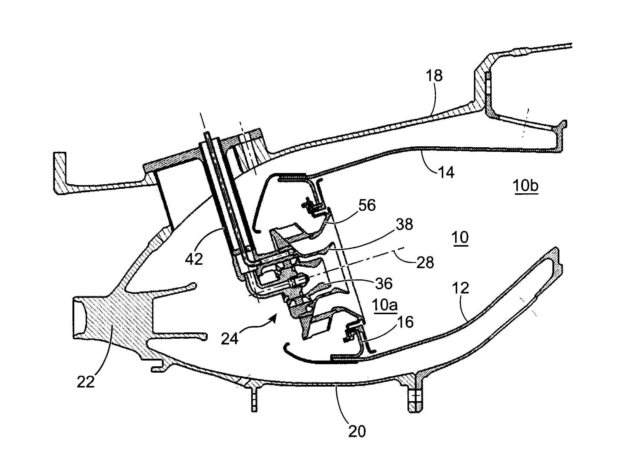
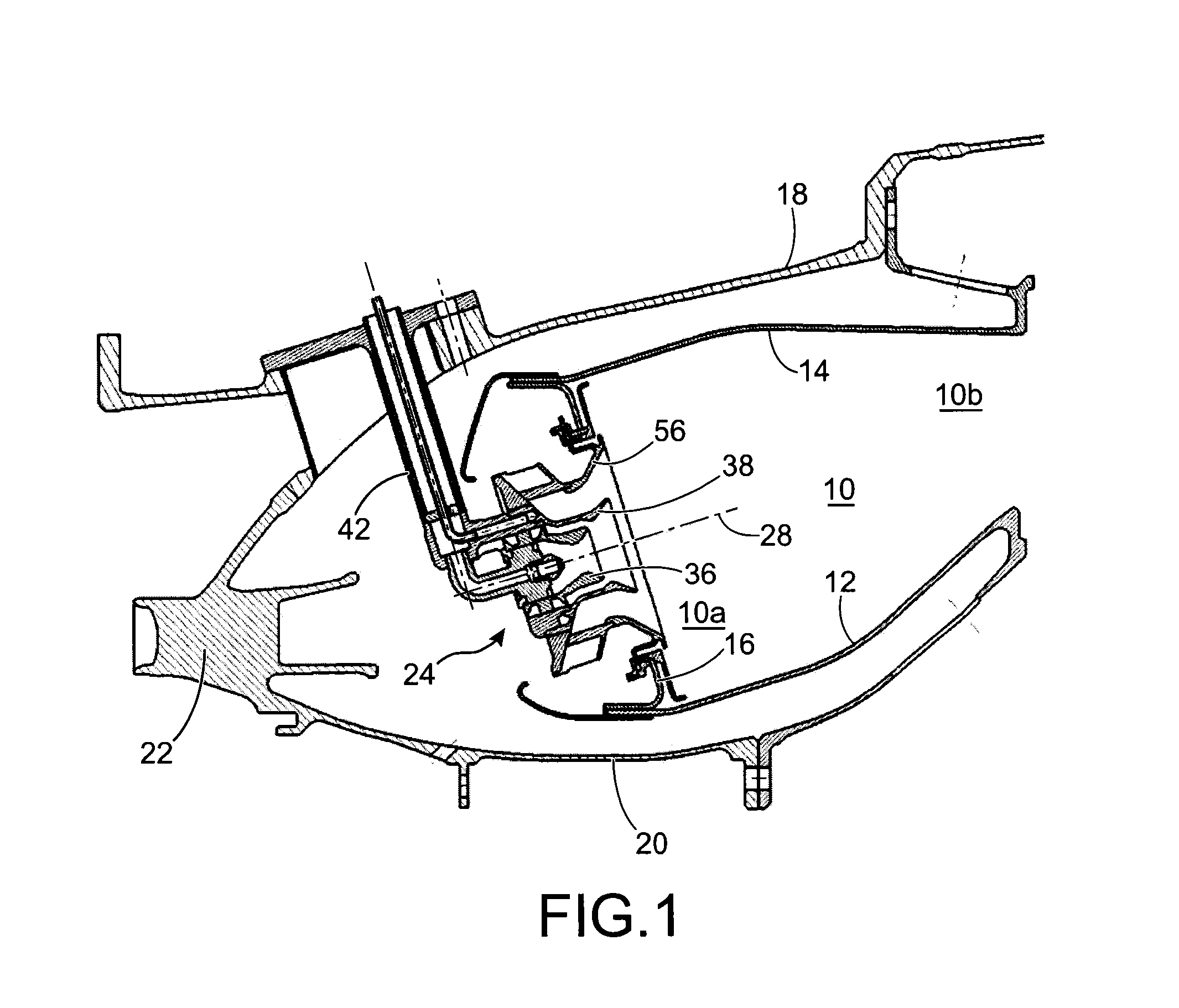
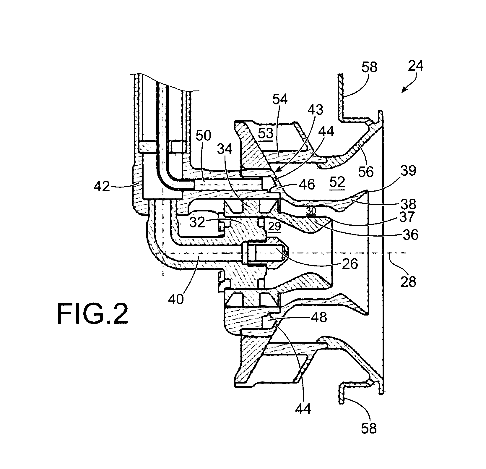
[0027]To this end the invention proposes an air and fuel injection system for the back of a turbomachine's annular chamber, including at least two coaxial fuel injection devices, including a central injector emerging in a central channel designed for the admission of a stream of air intended to be blended in said injection system with fuel from said central injector, together with a peripheral annular injector including at least one fuel ejection aperture made in an annular wall and emerging in a peripheral annular channel separated from said central channel by said annular wall, and having an annular space of admission of a stream of air intended to be blended in this peripheral channel with fuel delivered by the peripheral injector.

[0028]According to the invention, the injection system also includ...


PUM


Abstract

An air and fuel injection system for the back of a turbomachine's annular combustion chamber, including a central injector and a peripheral annular fuel injector including at least one fuel injection aperture made in an annular wall and emerging in a peripheral annular channel separated from a central channel by the annular wall and having an annular space of admission of air. The system also includes multiple air ejection apertures made in the annular wall downstream from the fuel ejection aperture or apertures in reference to the flow of the air stream, for an additional injection of air into the channel.

Description

TECHNICAL FIELD[0001]The present invention relates to the field of turbomachine combustion chambers, in particular in aircraft turbomachines, and more specifically concerns systems for injection of air and fuel into these combustion chambers.[0002]More specifically the invention concerns injection systems with a twin fuel injection circuit, which include a central injector, commonly called a pilot injector, delivering a permanent rate of flow of fuel optimised for low speeds, together with a peripheral annular injector, sometimes called the main injector, which delivers an intermittent rate of flow of fuel optimised for high speeds, where this peripheral injector is, for example, of the type commonly called a multipoint injector.[0003]These injection systems have been developed to enable combustion chambers to operate with a blend of air and fuel in which there is a low proportion of fuel, and more generally for improved adaptation of the injection of air and of fuel at the various ...

Claims


Application Information

Patent Timeline
Patent Type & Authority Applications(United States)
IPC IPC(8): F23R3/28F02C7/22
CPCF23D2900/00015Y02T50/675F23R3/343F23R3/14Y02T50/60F23D2900/11101F23R3/04F23R3/286
Inventor HERNANDEZ, DIDIER HIPPOLYTENOEL, THOMAS OLIVER MARIERULLAUD, MATTHIEU FRANCOIS
Owner SN DETUDE & DE CONSTR DE MOTEURS DAVIATION S N E C M A
Why Eureka
Try Eureka