
System and method for probe-based high precision spatial orientation control and assembly of parts for microassembly using computer vision

a computer vision and spatial orientation technology, applied in the field of multiprobe microassembly, can solve the problems of positioning errors, chemical processes that are not always compatible, and mechanical regions that exist primarily in the plan

Active Publication Date: 2012-12-06
GOVERNMENT OF THE UNITED STATES OF AMERICA AS REPRESENTED BY THE SEC OF COMMERCE THE NAT INST OF STANDARDS & TEHCNOLOGY
View PDF7 Cites 6 Cited by
  • Summary
  • Abstract
  • Description
  • Claims
  • Application Information

AI Technical Summary

Benefits of technology

[0012]In another embodiment, a glue dispenser can be provided for placing glue onto a part prior to placement within a slot. In still another embodiment, the plurality of probes is supported by a plurality of nanopositioners configured to provide six degrees of spatial motion. In another embodiment, the plurality of probes may be mounted on stages having three degrees of freedom. In still another embodiment, the plurali...

Problems solved by technology

While this is adequate for many devices, it results in mechanical regions that exist primarily in the plane and do not have fully spatial mechanisms with significant depth of stacked parts.
Also, the chemical processes are also not always compatible with materials that would be desirable to use with a mechanical device.
Additionally, there are numerous sources for positioning errors in mircroassembly design and manufacturing, where parts often need to be placed within micron and even submicron tolerances.
For example, electrostatic forces can cause a micro part to “stick” to a gripping mechanism during release, thus affecting the final positioning.
Much of the current microassembly technology lacks the capability to manipulate micro parts in a dexterous manner required for such high precision placement.
Such technologies, however, are limited with respect to part manipulation dexterity, accuracy, robustness, and part variability, among others.

Method used


Image

  • System and method for probe-based high precision spatial orientation control and assembly of parts for microassembly using computer vision
  • System and method for probe-based high precision spatial orientation control and assembly of parts for microassembly using computer vision
  • System and method for probe-based high precision spatial orientation control and assembly of parts for microassembly using computer vision

Examples


Embodiment Construction

[0017]The embodiments will now be described more fully hereinafter with reference to the accompanying drawings, in which illustrative embodiments of the invention are shown. The embodiments disclosed herein can be embodied in many different forms and should not be construed as limited to the embodiments set forth herein; rather, these embodiments are provided so that this disclosure will be thorough and complete and will fully convey the scope of the invention to those skilled in the art. Unnecessary detail of known functions and operations may be omitted from the current description so as not to obscure the present invention. Like numbers refer to like elements throughout. As used herein, the term “and / or” includes any and all combinations of one or more of the associated listed items.

[0018]The terminology used herein is for the purpose of describing particular embodiments only and is not intended to be limiting of the invention. As used herein, the singular forms “a”, “an” and “th...


PUM


Abstract

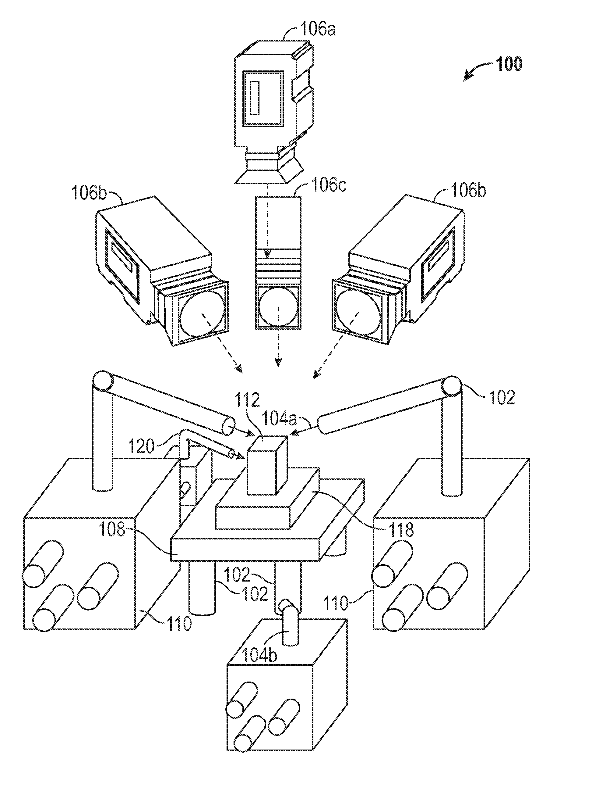
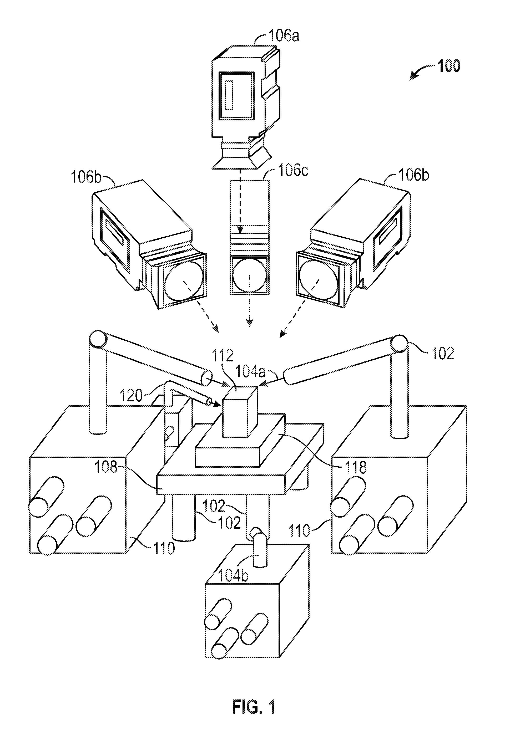
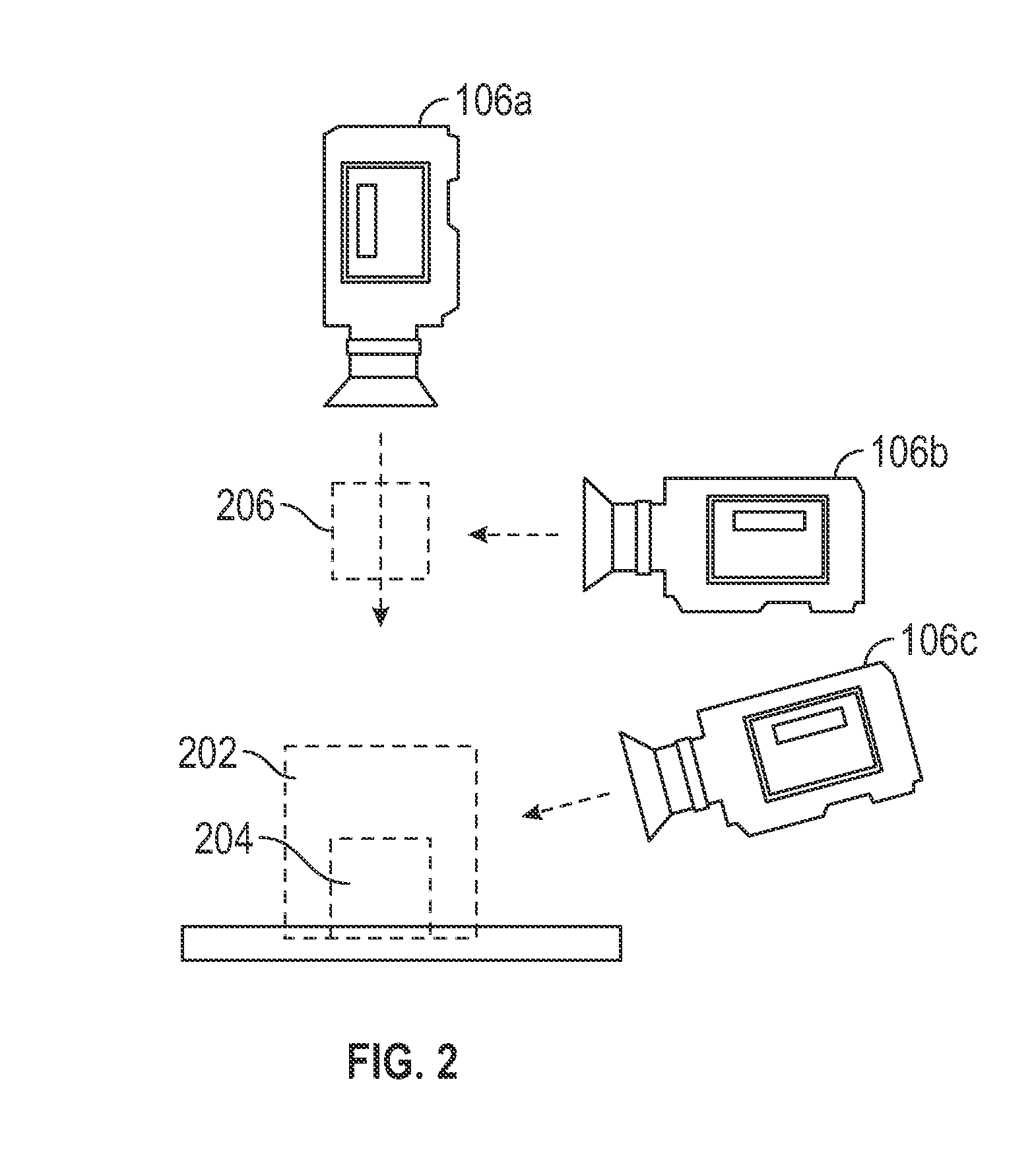
A microassembly method and system utilizing multiple probes. Multiple manipulation actuators can be utilized for maintaining / holding one or more probes and an assembly substrate. Multiple microscope cameras can be configured to provide three distinct workspace configurations. At the center of each manipulation actuator is a die stage, which supports the assembly substrate upon which parts are assembled. A glue dispenser can also provide glue to a part prior to placement.

Description

CROSS-REFERENCE TO PROVISIONAL APPLICATION[0001]The present application claims benefit of priority under 35 U.S.C. 119(e) of U.S. Provisional Patent Application Ser. No. 61 / 519,851, filed on May 31, 2011, which is incorporated herein by reference in its entirety.TECHNICAL FIELD[0002]Embodiments are further related to multi-probe microassembly. Embodiments are also related to a method of multi-probe microassembly using computer vision.BACKGROUND OF THE INVENTION[0003]As microelectromechanical systems (MEMS) become functionally more complex, the need for assembly devices and methods that can accomplish more complex structures is apparent. Current production technologies primary use a single wafer that is processed chemically to produce finished devices. While this is adequate for many devices, it results in mechanical regions that exist primarily in the plane and do not have fully spatial mechanisms with significant depth of stacked parts. Also, the chemical processes are also not alw...

Claims


Application Information

Patent Timeline
IPC IPC(8): G01D21/00
CPCB81C1/00063
Inventor WASON, JOHNWEN, JOHN T.GORMAN, JASONDAGALAKIS, NICHOLAS
Owner GOVERNMENT OF THE UNITED STATES OF AMERICA AS REPRESENTED BY THE SEC OF COMMERCE THE NAT INST OF STANDARDS & TEHCNOLOGY
Learn More