Condenser

a technology of condenser and super-cooler, which is applied in the direction of indirect heat exchangers, refrigeration components, lighting and heating apparatus, etc., can solve the problems of inability to achieve the improvement of refrigerant condensation efficiency and super-cooling efficiency, and achieve the effect of increasing the width of the stable rang

Inactive Publication Date: 2012-12-06
KEIHIN THERMAL TECH CORP
View PDF8 Cites 4 Cited by
  • Summary
  • Abstract
  • Description
  • Claims
  • Application Information

AI Technical Summary

Benefits of technology

[0008]In view of the above-described circumstances, an object of the present invention is to provide a condenser which can increase the width of the stable range while securing its performance to the greatest degree.
[0014]According to a condenser according to pars. 1) to 3), a first header tank to which all the heat exchange tubes of the condensation part are connected and a second header tank to which all the heat exchange tubes of the super-cooling part are connected are provided at one of left and right ends of the condenser; the first header tank has one communication section which communicates with the second header tank through a communication part and to which all the heat exchange tubes forming one heat exchange path are connected; the communication part is provided at a height below the uppermost heat exchange tube among all the heat exchange tubes connected to the communication section; the second header tank is disposed on the outer side of the first header tank with respect to the left-right direction; an upper end of the second header tank is located above a lower end of the first header tank; the second header tank has a function of separating gas and liquid from each other and storing the separated liquid; and all the refrigerant having passed through the heat exchange tubes of the condensation part flows into the communication section of the first header tank and flows into the second header tank through the communication part. Thus, when refrigerant within the communication section of the first header tank reaches the communication part during charging thereof, the refrigerant flows into the second header tank through the communication part and then flows into the heat exchange tubes of the refrigerant super-cooling path. Therefore, as compared with the case where the refrigerant within the communication section flows into the second header tank after reaching the uppermost heat exchange tube among all the heat exchange tubes connected to the communication section, the interiors of the heat exchange tubes forming the refrigerant super-cooling path can be filled with liquid-phase refrigerant at an early stage. Therefore, the width of a stable range within which a constant degree of super cooling is attained; i.e., the width of a range regarding the refrigerant charge amount within which a constant degree of super cooling is attained, increases. As a result, a super-cooling characteristic which is more stable against load fluctuation and / or leakage of refrigerant can be attained, and the performance of a car air conditioner using this condenser can be maintained for a long period of time.
[0015]Also, since the length of the heat exchange tubes of all the heat exchange paths of the super-cooling part becomes greater than the length of the heat exchange tubes of all the heat exchange paths of the condensation part, as compared with the condenser disclosed in the above-mentioned publication, the area of the heat exchange section increases, and the refrigerant super-cooling efficiency increases.

Problems solved by technology

Therefore, in the case where the dimensions of the condenser, including the liquid receiver, as measured in the vertical direction and the left-right direction are fixed to certain dimensions, the areas of the heat exchange portions of the condensation part and the super-cooling part become insufficient, and further improvement of the refrigerant condensation efficiency and the refrigerant super-cooling efficiency cannot be attained.

Method used


Image

  • Condenser
  • Condenser
  • Condenser

Examples


Embodiment Construction

[0035]Embodiments of the present invention will next be described with reference to the drawings.

[0036]In the following description, the reverse side of the sheet on which FIG. 1 is drawn will be referred to as the “front,” and the opposite side as the “rear.”

[0037]The term “aluminum” as used in the following description encompasses aluminum alloys in addition to pure aluminum.

[0038]Like portions and components are denoted by like reference numerals throughout the drawings, and they will not be described redundantly.

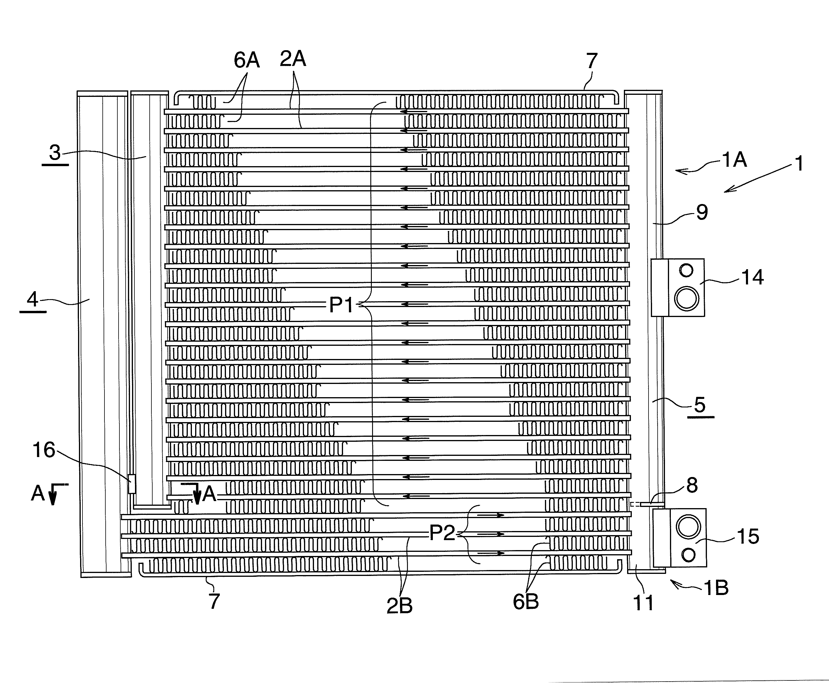
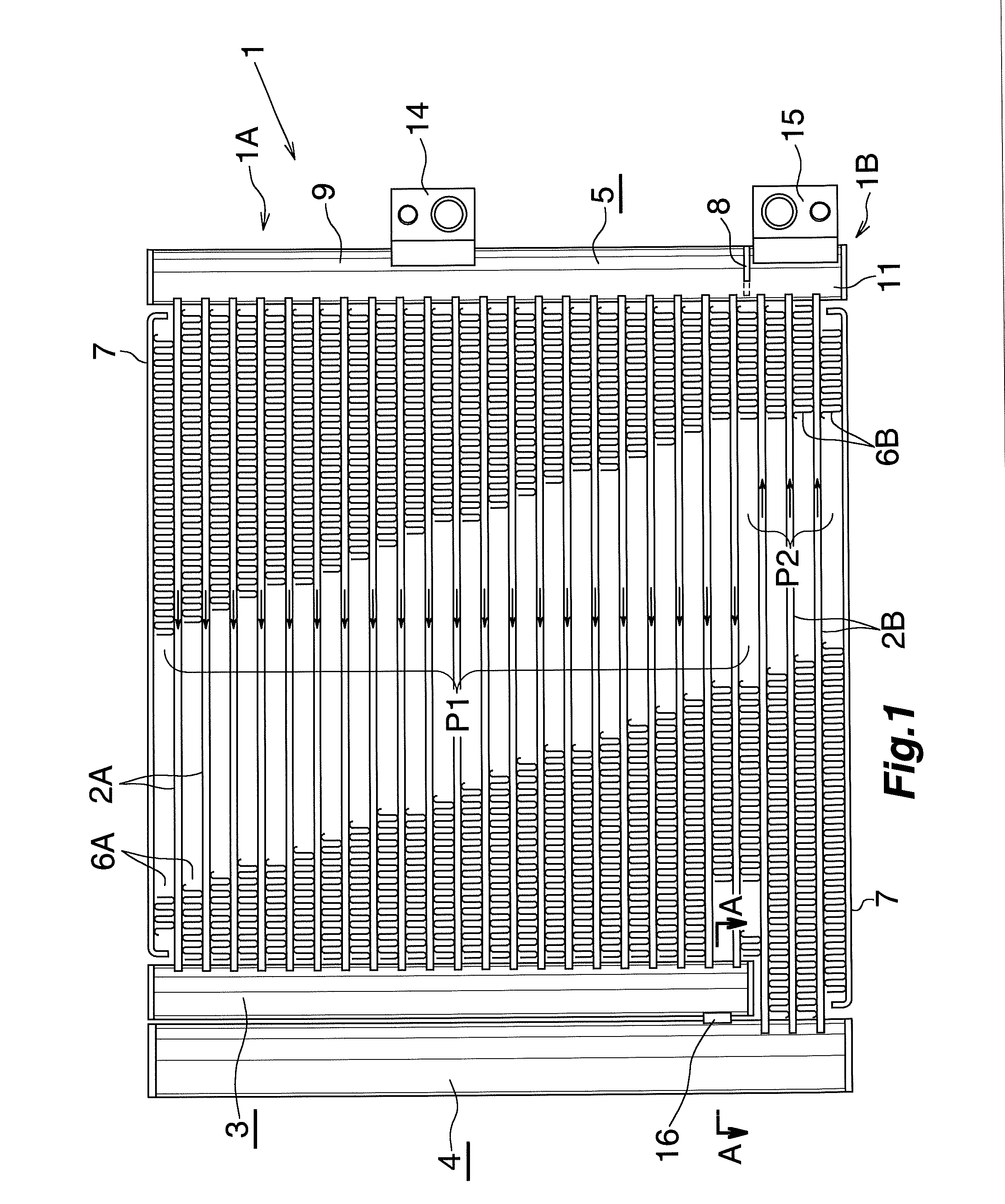
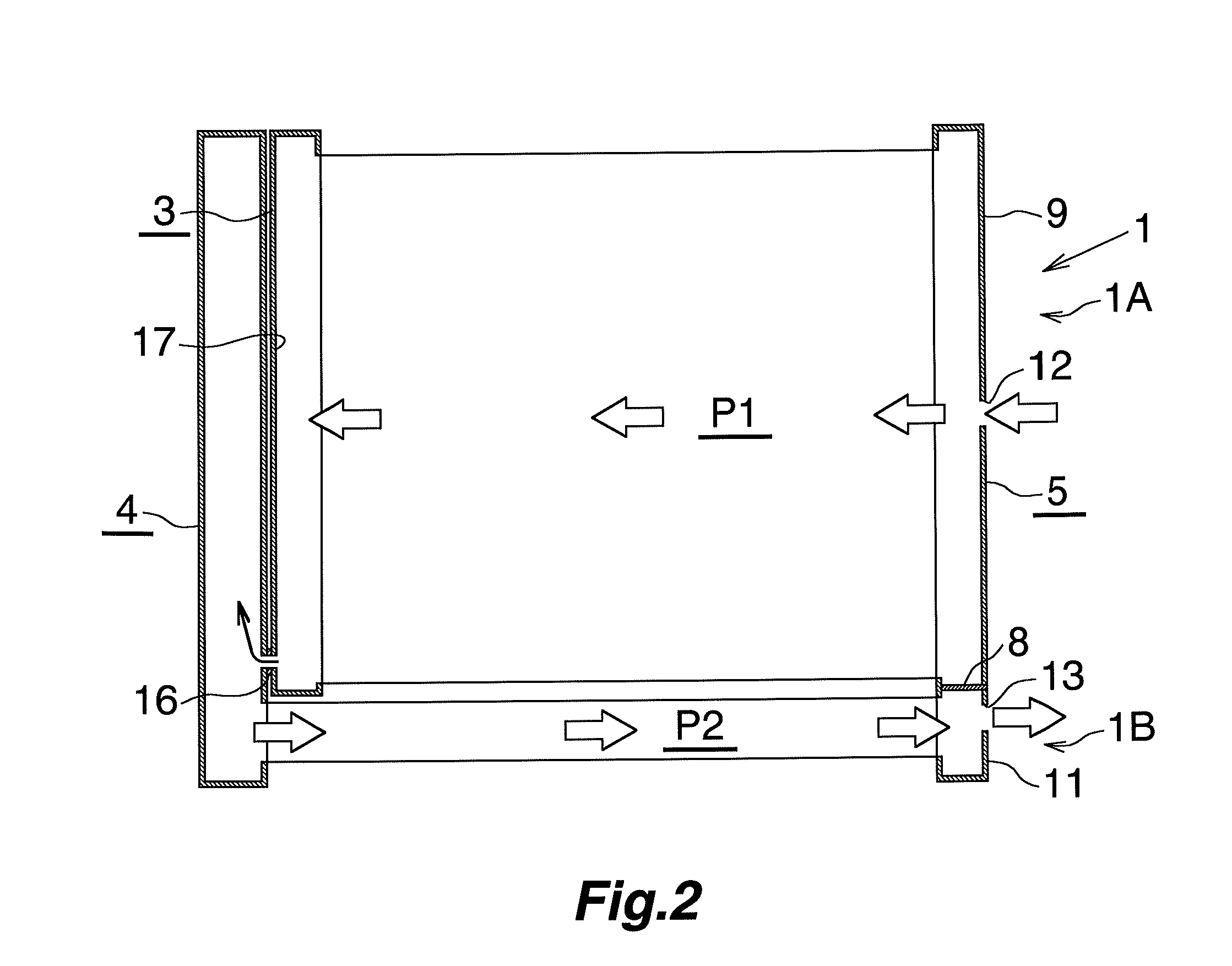
[0039]FIG. 1 specifically shows the overall structure of a first embodiment of a condenser according to the present invention. FIG. 2 schematically shows the condenser of FIG. 1. FIGS. 3 and 4 show the structure of a main portion of the condenser of FIG. 1. In FIG. 2, individual heat exchange tubes are not illustrated, and corrugate fins, side plates, a refrigerant inlet member, and a refrigerant outlet member are also not illustrated.

[0040]In FIGS. 1 and 2, a condenser ...


PUM


Abstract

A condenser includes first and second header tanks provided at one end thereof such that the latter is located on the outer side of the former. First heat exchange tubes forming a first heat exchange path provided in a condensation part are connected to the first header tank. Second heat exchange tubes forming a second heat exchange path provided in a super-cooling part are connected to the second header tank. The first header tank has one communication section which communicates with the second header tank through a communication part and to which all the heat exchange tubes forming the first heat exchange path are connected. The communication part is provided at a height below the uppermost heat exchange tube among all the heat exchange tubes connected to the communication section. The upper end of the first header tank is located above the lower end of the second header tank.

Description

BACKGROUND OF THE INVENTION[0001]The present invention relates to a condenser suitable for use in, for example, a car air conditioner mounted on an automobile.[0002]Herein and in the appended claims, the upper side, lower side, left-hand side, and right-hand side of FIGS. 1 and 2 will be referred to as “upper,”“lower,”“left,” and “right,” respectively.[0003]A condenser for a car air conditioner is known (see Japanese Patent Application Laid-Open (kokai) No. 2001-33121). The known condenser has a condensation part and a super-cooling part provided such that the former is located above the latter. The condenser includes a plurality of heat exchange tubes disposed in parallel such that their length direction coincides with the left-right direction and they are spaced apart from one another in the vertical direction; fins each disposed between adjacent heat exchange tubes; and header tanks which are disposed such that their length direction coincides with the vertical direction and to w...

Claims


Application Information

Patent Timeline
Patent Type & Authority Applications(United States)
IPC IPC(8): F28F9/02
CPCF25B39/04F25B2339/0442F25B2339/0444F28D2021/0084F28F9/268F28D1/05391F25B2339/0446
Inventor ARINO, KOUTATOKIZAKI, KAZUMIHANAFUSA, TATSUYA
Owner KEIHIN THERMAL TECH CORP
Why Eureka
Try Eureka