Subsea pressure relief devices and methods

a pressure relief device and subsea technology, applied in the field of burst disc assemblies, can solve the problems of unanticipated high fluid pressure entering the production system, imbalance of pressure, and pressure in the system,

Inactive Publication Date: 2012-12-06
BP CORP NORTH AMERICA INC +1
View PDF10 Cites 24 Cited by
  • Summary
  • Abstract
  • Description
  • Claims
  • Application Information

AI Technical Summary

Benefits of technology

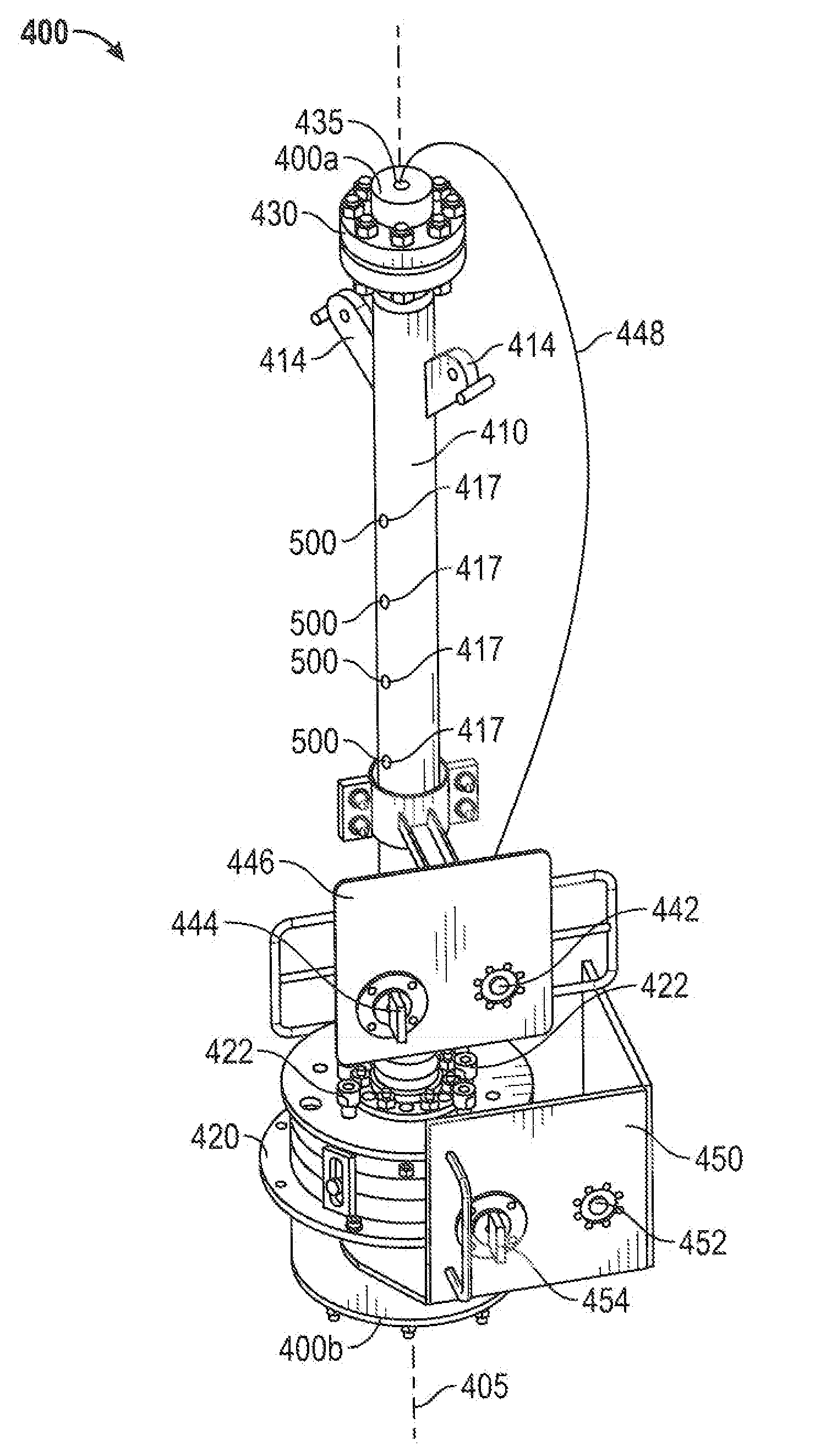
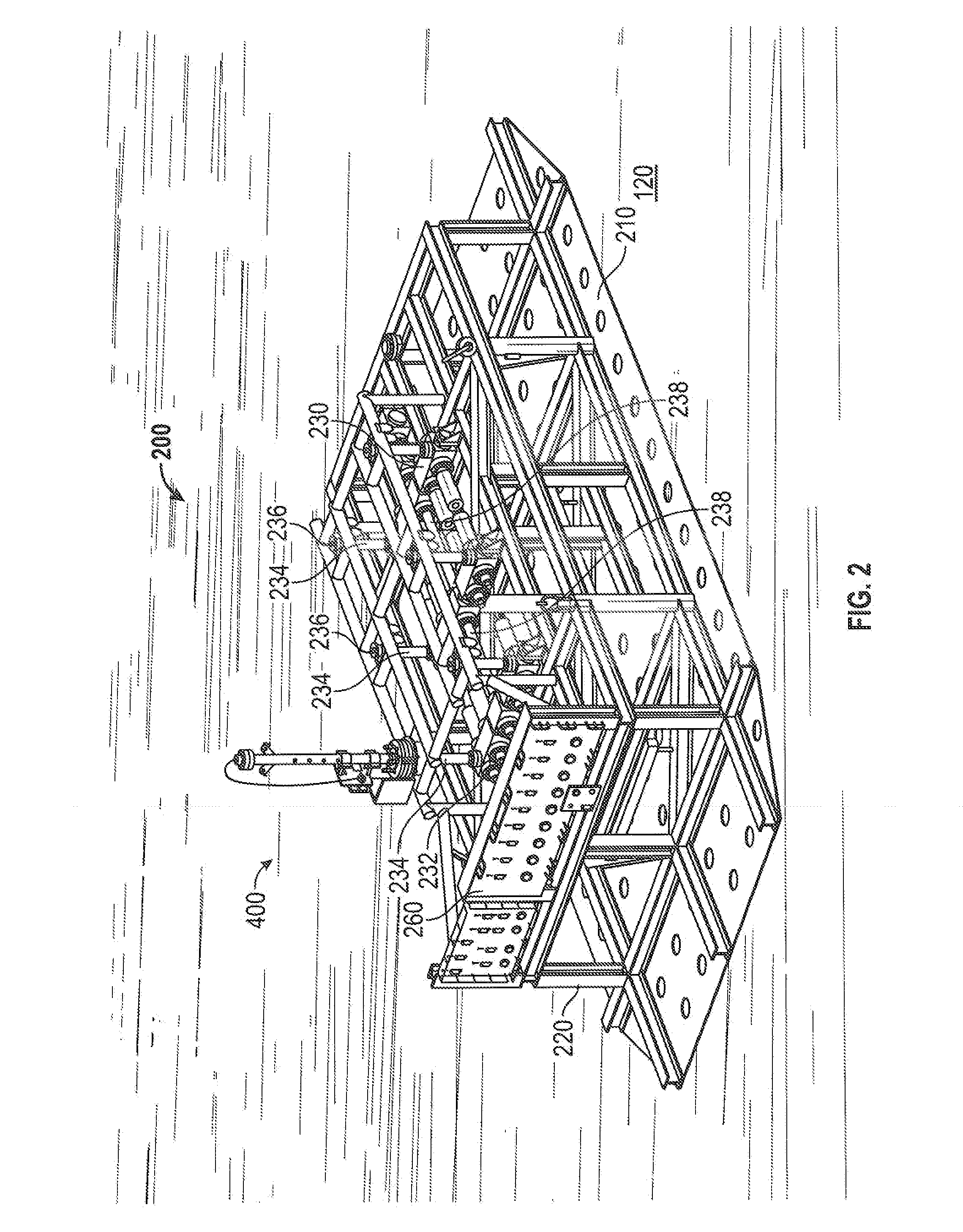
[0014]These and other needs in the art are addressed in another embodiment by a device for relieving pressure in a subsea fluid conduit. In an embodiment, the device comprises a manifold including an inlet end and a plurality of outlet ends. In addition, the device comprises a connector coupled to the inlet end of the manifold. The connector is configured to releasably engage a mating connector coupled to the fluid conduit. Further, the device comprises a plurality of valve spools. Each valve spool is coupled to one of the outlet ends of the manifold. Each valve spool includes a valve configure to control a flow of fluids through the corresponding valve spool. Still further, the de

Problems solved by technology

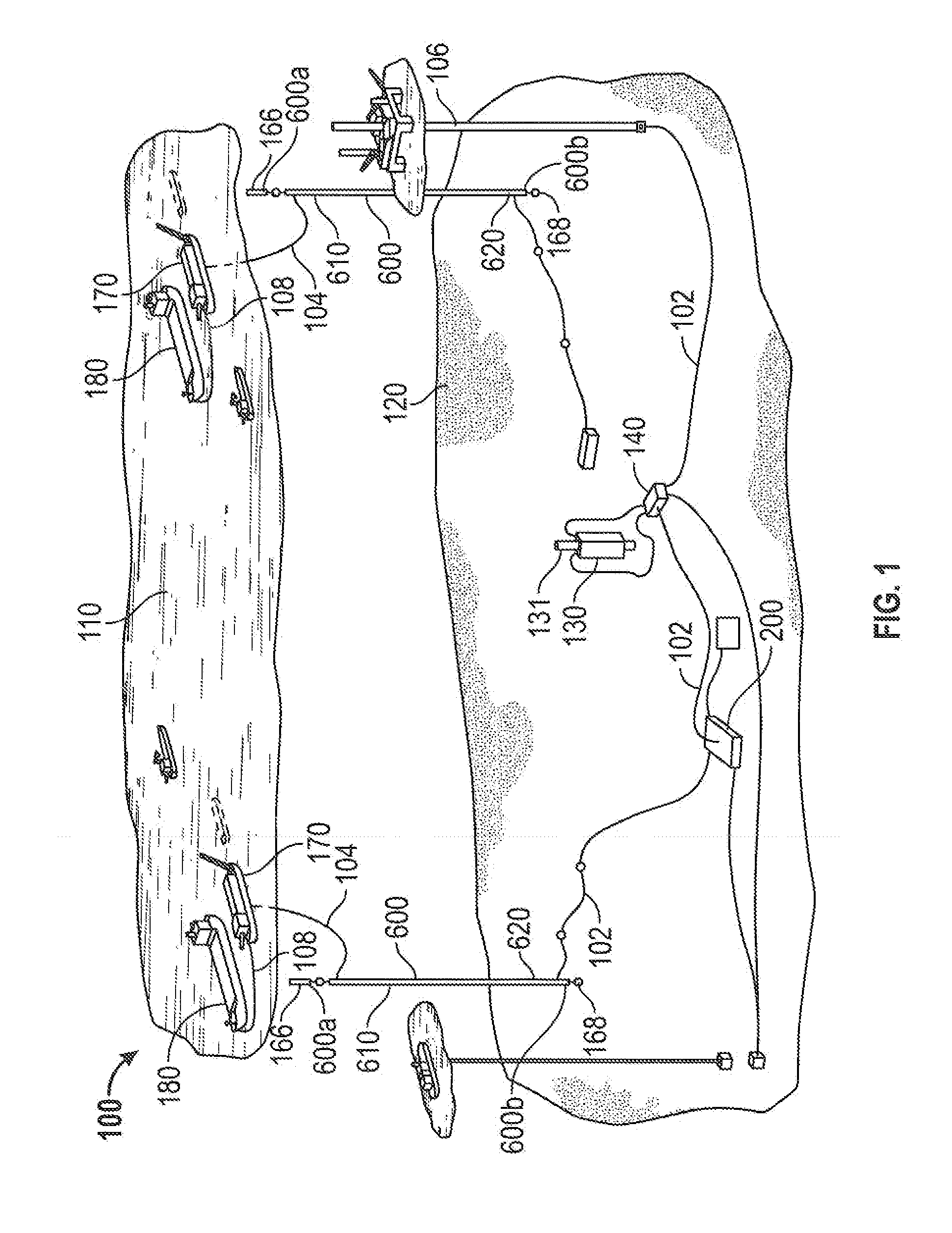
However, such pressures may be erratic, resulting in unanticipated high fluid pressures entering the production system and possibly over pressurizing components of the pressure containment system.
Moreover, back pressure within the pressure containment system may be generated by closing valves or from other processes, which may lead to an over pressurization of equipment in the system.
Such an imbalance of pressures could also build up due to hydrate formation, sudden pressure changes in the well bore, or back pressure from valve closings or other processes performed on the system.
The reliance on operator intervention may be problema

Method used


Image

  • Subsea pressure relief devices and methods
  • Subsea pressure relief devices and methods
  • Subsea pressure relief devices and methods

Examples


Embodiment Construction

[0031]The following discussion is directed to various exemplary embodiments. However, one skilled in the art will understand that the examples disclosed herein have broad application, and that the discussion of any embodiment is meant only to be exemplary of that embodiment, and not intended to suggest that the scope of the disclosure, including the claims, is limited to that embodiment.

[0032]Certain terms are used throughout the following description and claims to refer to particular features or components. As one skilled in the art will appreciate, different persons may refer to the same feature or component by different names. This document does not intend to distinguish between components or features that differ in name but not function. The drawing figures are not necessarily to scale. Certain features and components herein may be shown exaggerated in scale or in somewhat schematic form and some details of conventional elements may not be shown in interest of clarity and concis...


PUM


Abstract

A device for relieving pressure in a subsea component comprises a housing including an inner cavity, an open end in fluid communication with the inner cavity, and a through bore extending from the inner cavity to an outer surface of the housing. In addition, the device comprises a connector coupled to the open end. The connector is configured to releasably engage a mating connector coupled to the subsea component. Further, the device comprises a burst disc assembly mounted to the housing within the through bore. The burst disc assembly is configured to rupture at a predetermined differential pressure between the inner cavity and the environment outside the housing.

Description

CROSS-REFERENCE TO RELATED APPLICATIONS[0001]This application claims benefit of U.S. provisional patent application Ser. No. 61 / 493,752 filed Jun. 6, 2011, and entitled “Subsea Pressure Relief Device,” which is hereby incorporated herein by reference in its entirety.STATEMENT REGARDING FEDERALLY SPONSORED RESEARCH OR DEVELOPMENT[0002]Not applicable.BACKGROUND[0003]1. Field of the Invention[0004]The disclosure relates generally to systems and methods for managing over pressurization of subsea equipment. More particularly, the disclosure relates to burst disc assemblies and methods of using such assemblies to relieve excessive fluid pressure in subsea equipment such as conduits, pipelines, and fluid containment devices.[0005]2. Background of the Technology[0006]In producing oil and gas from offshore wells, an offshore production system includes flowing hydrocarbons from a subterranean formation through a production string to a wellhead at the sea floor. From the wellhead, hydrocarbons...

Claims


Application Information

Patent Timeline
IPC IPC(8): E21B33/00
CPCE21B33/035E21B17/01E21B41/0021
Inventor BALLARD, ADAM LEEFRANKLIN, ROBERT WINFIELDGULGOWSKI, JR., PAUL WILHELMOLDFIELD, TONYPABON, MARTIN JULIO
Owner BP CORP NORTH AMERICA INC
Why Eureka
Try Eureka