
Image processing apparatus, image processing method and program

a technology of image processing and image processing method, applied in the field of image processing apparatus, can solve the problems of low resolution, low resolution of plenoptic camera, and so on, and achieve the effect of suppressing the loss of signal due to the aperture effect and improving image quality

Active Publication Date: 2012-12-06
CANON KK
View PDF11 Cites 102 Cited by
  • Summary
  • Abstract
  • Description
  • Claims
  • Application Information

AI Technical Summary

Benefits of technology

[0009]According to the present invention, loss of signal due to the aperture effect is suppressed, and a high-resolution image with an image quality higher than a conventional image is generated.

Problems solved by technology

Generally, for a camera array provided by arranging multiple small cameras, the number of pixels for each camera is small and the resolution is low because of the camera size.
Furthermore, compared with an ordinary camera that has the same number of pixels, a plenoptic camera has a low resolution.
As a result, so-called folding noise (or aliasing) occurs.
As will be later described in detail, the influence of the aperture effect is very strong, depending on a frequency, and may cause the original signal to be attenuated, and buried in noise.
When the super-resolution processing is performed to recover the high-frequency component of a signal that is attenuated, the attenuated signal is buried in noise and, in actuality, is lost, and therefore, a high quality, high resolution image can not be obtained.

Method used


Image

  • Image processing apparatus, image processing method and program
  • Image processing apparatus, image processing method and program
  • Image processing apparatus, image processing method and program

Examples


Embodiment Construction

General Arrangement of Image Processing Apparatus

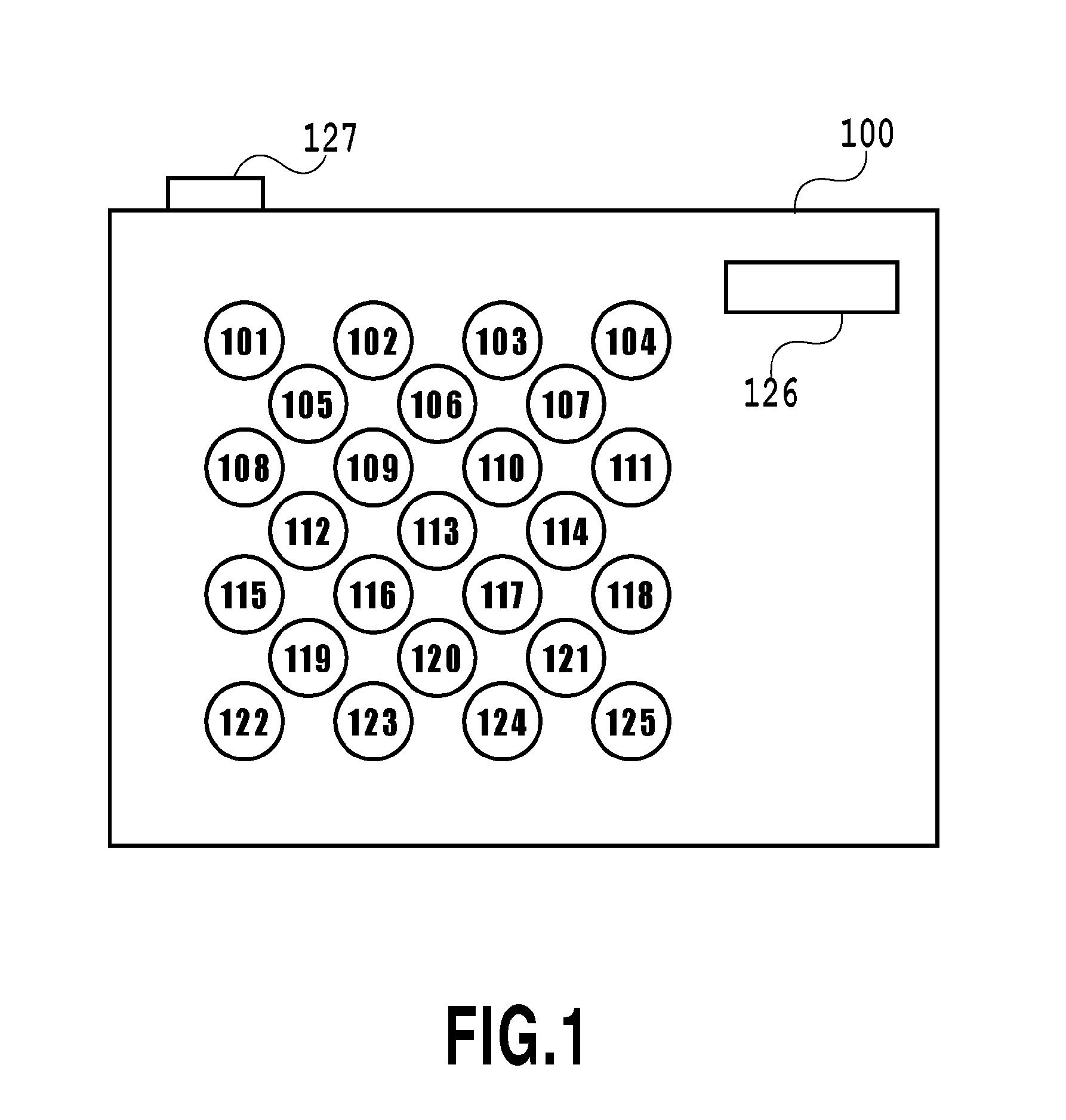
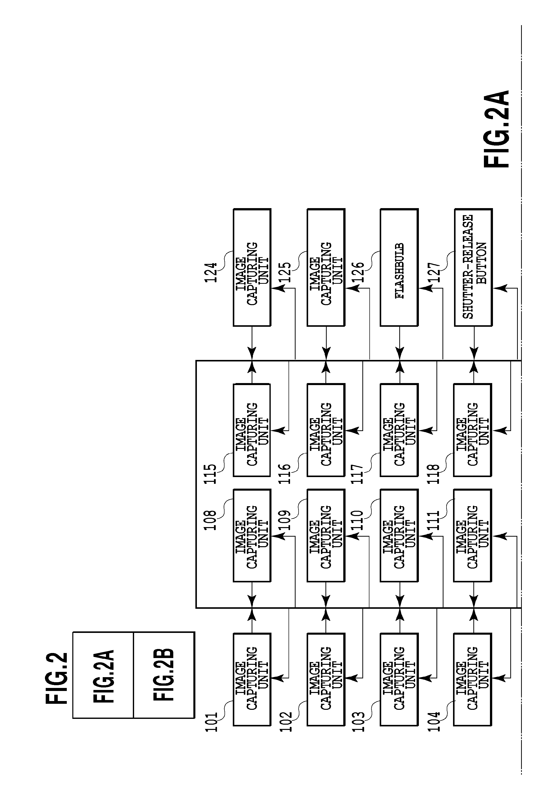
[0022]FIG. 1 is a diagram illustrating a general view of an image capturing apparatus (image processing apparatus) 100 according to one embodiment of the present invention. The image capturing apparatus 100 is a so-called camera array (also known as a camera array system, a multiple lens camera or the like) where 25 image capturing units 101 to 125 are provided on the front face (on the side nearest a subject). The image capturing unit 100 also includes a flash bulb 126 and a shutter-release button 127, and further includes, although not shown in FIG. 1, an operating unit and a display unit on the rear face.

[0023]The number of image capturing units is not limited to 25, and an arbitrary number of image capturing units, more than one, may be provided. Further, a plurality of image capturing units are not necessarily arranged on the same face, and can be arbitrarily arranged so long as the same subject, or substantially the same region,...


PUM


Abstract

When the super-resolution processing is performed, loss of signal occurs due to the aperture effect, and adversely affects the image quality. In order to improve the image quality by suppressing the occurrence of loss of signal, a pixel aperture characteristic provided for some of image capturing units differs from a pixel aperture characteristic provided for the other image capturing units, and a plurality of digital images are captured by these image capturing units and are synthesized thereafter.

Description

BACKGROUND OF THE INVENTION[0001]1. Field of the Invention[0002]The present invention relates to an image processing apparatus for employing image data obtained by a plurality of image capturing units, and an image processing method therefor.[0003]2. Description of the Related Art[0004]An image processing apparatus and an image processing method have been proposed whereby a focal length and a diaphragm can be altered after an image has been captured. As an example, disclosed in “Light Field Photography with a Hand-Held Plenoptic Camera”, R. Ng, M. Levoy, et al. , Stanford University Computer Science Tech Report CSTR 2005-02, are the configuration of a plenoptic camera that records the status of light fields inside an optical image capturing system, and a development method for subsequently altering a focal length (hereinafter referred to as “refocusing”) . Further, in “Dynamically Reparameterized Light Fields”, Isaksen et al., ACM SIGGRAPH, pp. 297-306 (2000), a method is disclosed ...

Claims


Application Information

Patent Timeline
IPC IPC(8): H04N5/228H04N13/232
CPCH04N2013/0088G06T5/50G06T2200/21G06T1/0007H04N5/3696H04N13/0232G06T2207/10052H04N13/232H04N23/633H04N23/631H04N25/702
Inventor YAHATA, KAZUHIRO
Owner CANON KK
Learn More