Laminate thermal insulation blanket for aircraft applications and process therefor

Inactive Publication Date: 2012-12-06
MRA SYST
View PDF8 Cites 31 Cited by
  • Summary
  • Abstract
  • Description
  • Claims
  • Application Information

AI Technical Summary

Benefits of technology

[0010]A technical effect of the invention is the ability of the thermal insulation blanket to protect nacelle structures, for example, composite core cowls, from engine fires and to maintain composite nacelle structures at temperatures that are not detrimental to the strength structural integrity of the structures. The thermal insulation blanket is capable of performing these roles at

Problems solved by technology

The potential for hot air leakage between the insulation blanket 50 and the remainder of the core cowl 36 can create a hazard if bond line temperatures of the cowl 36 are exceeded.
As operating temperatures have increased with newer engine designs, the increasingly severe

Method used


Image

  • Laminate thermal insulation blanket for aircraft applications and process therefor
  • Laminate thermal insulation blanket for aircraft applications and process therefor
  • Laminate thermal insulation blanket for aircraft applications and process therefor

Examples


Example

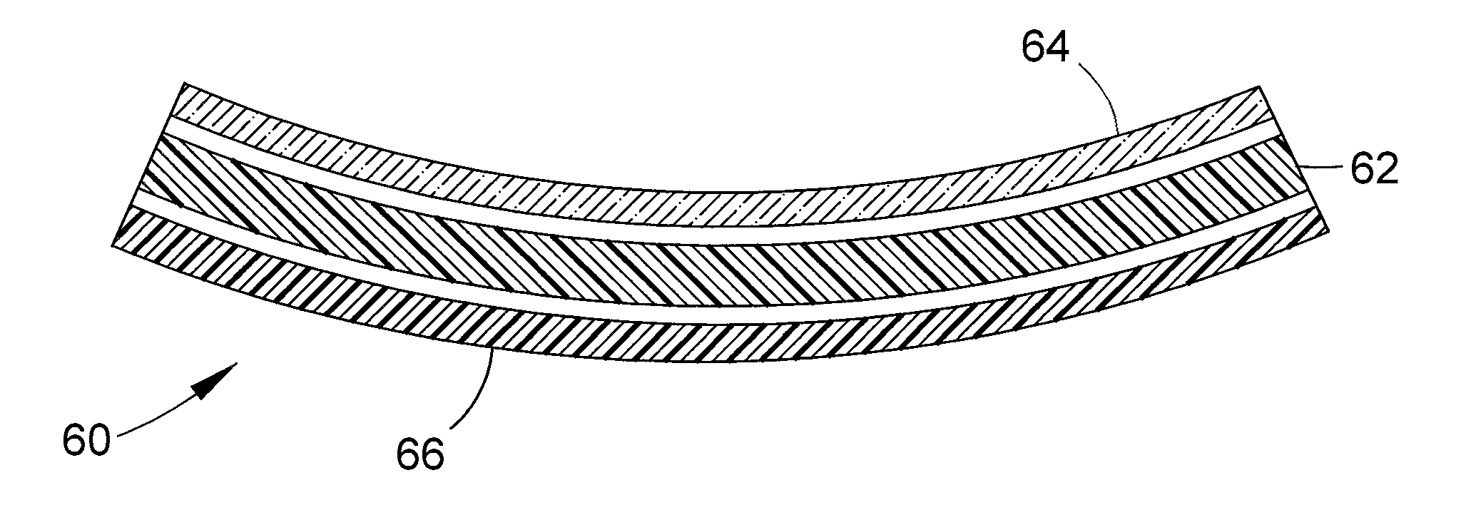
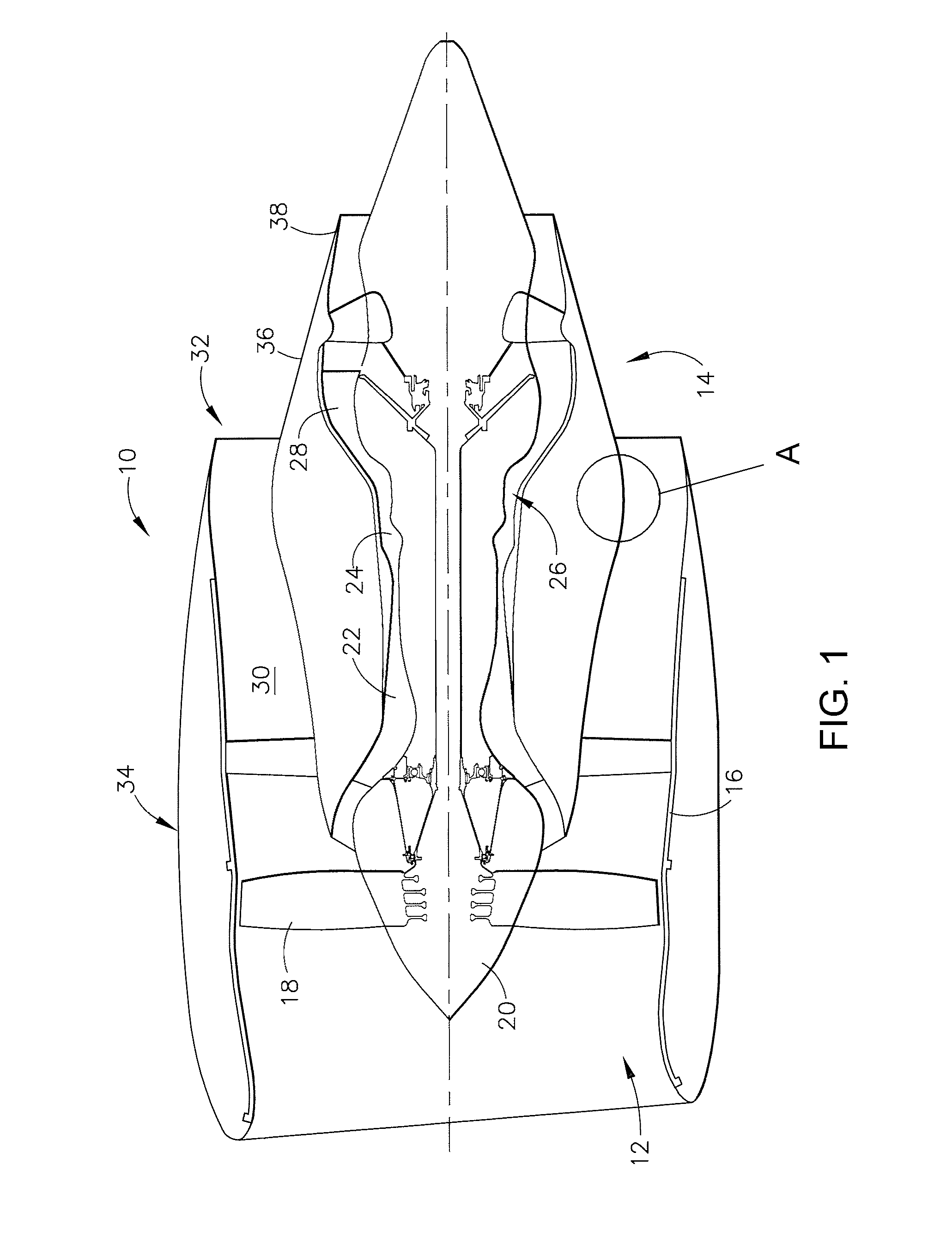
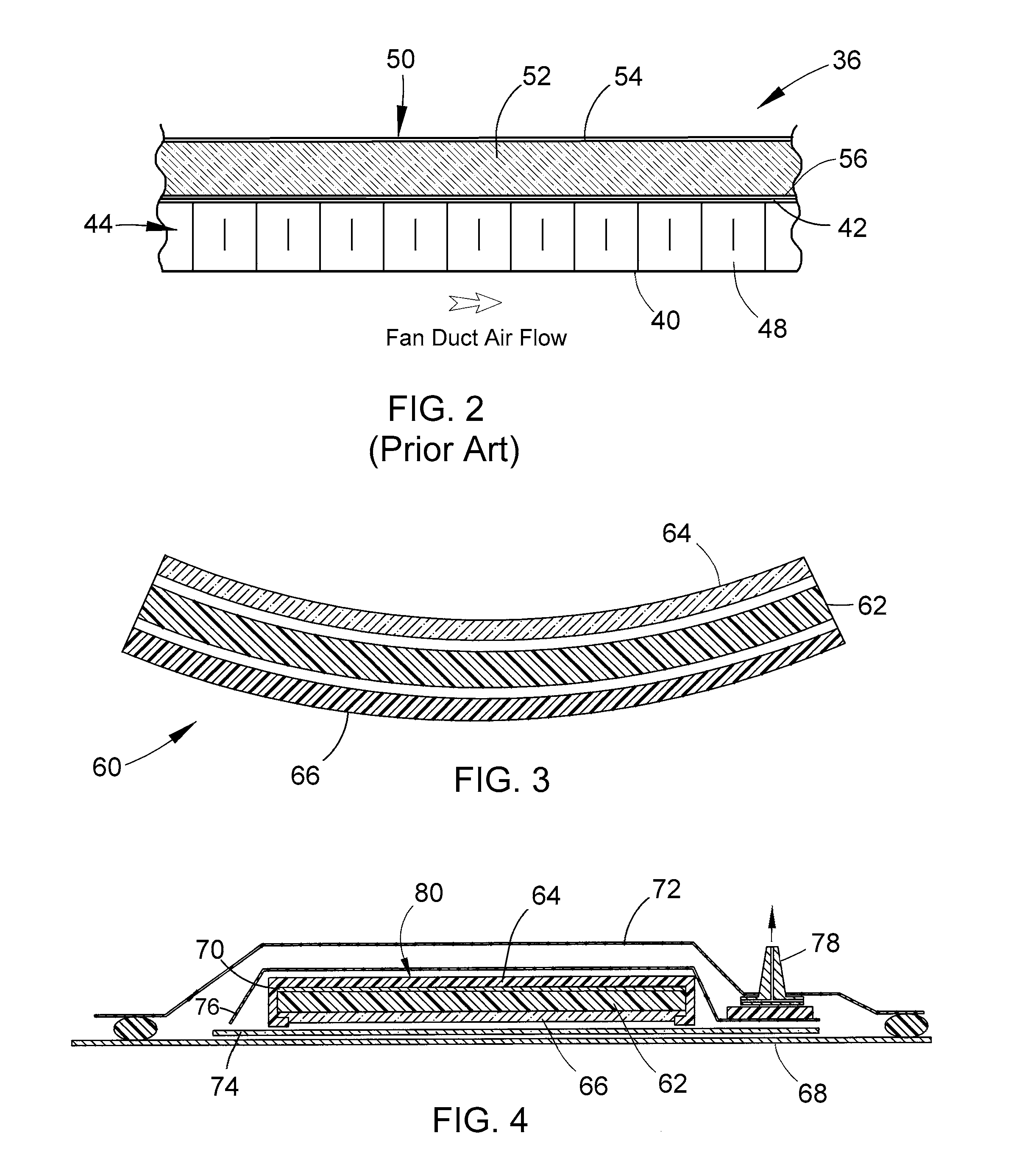
[0016]FIG. 3 represents a cross-section of a thermal insulation blanket 60 suitable for use in a high-bypass gas turbine engine, for example, of the type represented in FIG. 1. The thermal blanket 60 represented in FIG. 3 can be installed in place of the thermal insulation blanket 50 of FIG. 2, and therefore can be adapted for use with a core cowl 36. In particular, the thermal blanket 60 can be located on the interior face of the cowl 36 for the purpose of thermally protecting the layered structure (skins 40 and 42 and core 44) of the core cowl 36, similar to the manner represented and described for the prior art blanket 50 of FIG. 2. However, it is foreseeable that the thermal blanket 60 could be installed at other locations of the engine 10, as well as used in applications other than a high-bypass gas turbine engine.

[0017]The thermal blanket 60 represented in FIG. 3 has a layered construction that comprises an insulation material 62 bonded to and between a composite layer 64 and ...


PUM

PropertyMeasurementUnit
Percent by volumeaaaaaaaaaa
Temperatureaaaaaaaaaa
Volumeaaaaaaaaaa

Abstract

A thermal insulation blanket for an aircraft engine, and processes for producing the thermal insulation blanket to have low thermal conductivity and high temperature capability. The thermal insulation blanket has a layered construction that includes an aerogel insulation material, a composite layer disposed at a first surface of the aerogel insulation material, and a backing layer disposed at an opposite surface of the aerogel insulation material so that the aerogel insulation material is encapsulated between the composite and backing layers. The composite layer contains a resin matrix material reinforced with a fiber reinforcement material.

Description

BACKGROUND OF THE INVENTION[0001]The present invention generally relates to thermal insulation blankets of types used in aircraft engines. More particularly, the invention relates to a construction for a thermal insulation blanket that is suitable for surrounding a core engine of a high bypass gas turbine engine.[0002]FIG. 1 schematically represents a high-bypass turbofan engine 10 of a type known in the art. The engine 10 is schematically represented as including a fan assembly 12 and a core engine 14. The fan assembly 12 is shown as including a composite fan casing 16 and a spinner nose 20 projecting forwardly from an array of fan blades 18. Both the spinner nose 20 and fan blades 18 are supported by a fan disc (not shown). The core engine 14 is represented as including a high-pressure compressor 22, a combustor 24, a high-pressure turbine 26 and a low-pressure turbine 28. A large portion of the air that enters the fan assembly 12 is bypassed to the rear of the engine 10 to genera...

Claims


Application Information

Patent Timeline
IPC IPC(8): F04D29/40B32B37/06B32B3/00
CPCB64D33/02Y10T428/233B64D2033/0206
Inventor MAHESHWARI, MAHENDRAFANG, XIAOMEI
Owner MRA SYST
Why Eureka
Try Eureka