Slim type backlight unit

a backlight unit and slim technology, applied in lighting support devices, lighting and heating apparatus, instruments, etc., can solve the problems of increasing the manufacturing cost of the backlight unit, affecting the efficiency of the product, so as to reduce the thickness and weight, reduce the cost of mcpcb b>20/b>, and reduce the manufacturing cost. cost

Inactive Publication Date: 2007-06-21
SAMSUNG ELECTRONICS CO LTD
View PDF10 Cites 77 Cited by
  • Summary
  • Abstract
  • Description
  • Claims
  • Application Information

AI Technical Summary

Benefits of technology

[0015]The present invention has been made to solve the foregoing problems of the prior art and it is therefore an object according to certain embodiments of the present invention is to provide a backlight unit which has electrically-conducting parts with less thickness and weight, thereby achieving slimness and light weight, releasing heat generated from the LED package more quickly and reducing manufacturing costs.

Problems solved by technology

But this high output LED generates heat significantly and accordingly when mounted in e.g., a backlight unit with a small mounting area, heat from the LED fails to be released properly, thereby undermining efficiency of the product or causing malfunction.
In addition, the MCPCB 20 is expensive, thereby increasing manufacturing costs of the backlight unit.

Method used


Image

  • Slim type backlight unit
  • Slim type backlight unit
  • Slim type backlight unit

Examples


Embodiment Construction

[0028]Preferred embodiments of the present invention will now be described in detail with reference to the accompanying drawings.

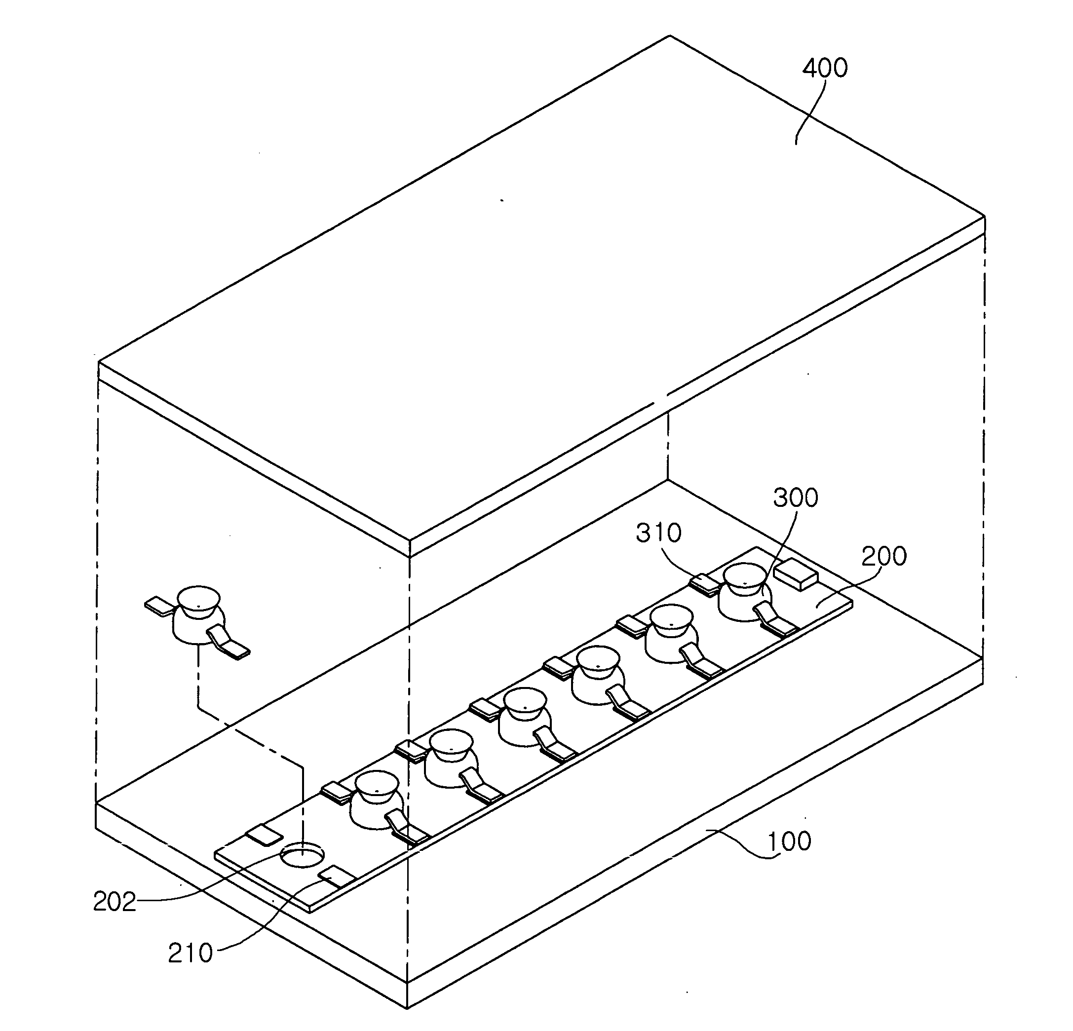
[0029]FIG. 3 is an exploded perspective view illustrating a backlight unit of the invention.

[0030]As show in FIG. 3, the backlight unit of the invention includes a bottom plate 100, a flexible printed circuit board 200, an LED package 300 and an optical sheet 400. The bottom plate 100 has each part mounted thereon. The flexible printed circuit board 200 has an electrically-conducting pattern formed on a top surface thereof and through holes 202 perforated therein. The flexible printed circuit board 200 is provided on the bottom plate 100. The LED package 300 is disposed on a top portion of the flexible printed circuit board corresponding to the through holes 202. The optical sheet 400 is disposed over the LED package 300 to evenly mix light generated from the LED package 300.

[0031]The LED package 300 includes lead frames 310 each having one portion connect...


PUM


Abstract

A backlight unit of the invention is reduced in thickness, weight and manufacturing costs but improved in heat releasing efficiency. In the backlight unit, a flexible printed circuit board has at least one through hole perforated therein. An LED package is disposed on a top portion of the flexible printed circuit board corresponding to the through hole. The backlight unit of the invention employs the flexible printed circuit board in place of a metal printed circuit board as a means to conduct current to the LED package. This produces a slimmer and lighter backlight unit and also saves manufacturing costs. In addition, the LED package is directly bonded onto a bottom plate by a heat conducting adhesive, thereby ensuring heat generated from the LED package to be released more quickly.

Description

CLAIM OF PRIORITY[0001]This application claims the benefit of Korean Patent Application No. 2005-124444 filed on Dec. 16, 2005 in the Korean Intellectual Property Office, the disclosure of which is incorporated herein by reference.BACKGROUND OF THE INVENTION[0002]1. Field of the Invention[0003]The present invention relates to a backlight unit incorporating a light emitting diode (LED) as a light source, and more particularly, to a slimmer backlight unit which is reduced in thickness, weight and manufacturing costs and improved in heat releasing efficiency.[0004]2. Description of the Related Art[0005]A light emitting diode (LED) converts an electrical signal into an infrared ray, visible light or other form by using properties of a compound, and is used for a signal transmitting / receiving device.[0006]In general, the LED is utilized in electronic home appliances, remote controllers, display boards, displays and various kinds of automation devices. The LED is largely broken down into ...

Claims


Application Information

Patent Timeline
Patent Type & Authority Applications(United States)
IPC IPC(8): F21V29/00F21V19/00F21Y101/02H01L33/64
CPCG02F1/133603H05K1/0206H05K1/189H05K3/0061F21V29/70H05K2201/0209H05K2201/09072H05K2201/10106F21V29/22H05K3/4069G02F1/1335
Inventor YOO, CHUL HEEAHN, HO SIK
Owner SAMSUNG ELECTRONICS CO LTD
Why Eureka
Try Eureka