Finger follower lever for actuating a gas exchange valve

Inactive Publication Date: 2012-12-13
SCHAEFFLER TECH AG & CO KG
View PDF1 Cites 11 Cited by
  • Summary
  • Abstract
  • Description
  • Claims
  • Application Information

AI Technical Summary

Benefits of technology

[0005]Starting from the prior art described above, it is then the object of the present invention to make available a finger follower lever for actuating a gas exchange valve which, on the one hand, allows good valve guidance in the region of the valve actuating surface and has a low mass and, on the othe

Problems solved by technology

In contrast, the finger follower lever in JP 07063013 A is not suitable for use in the region of restricted installation space conditions since the cam roller is of very wide configuration in the axial direction and the web is guided past

Method used


Image

  • Finger follower lever for actuating a gas exchange valve
  • Finger follower lever for actuating a gas exchange valve
  • Finger follower lever for actuating a gas exchange valve

Examples


Example

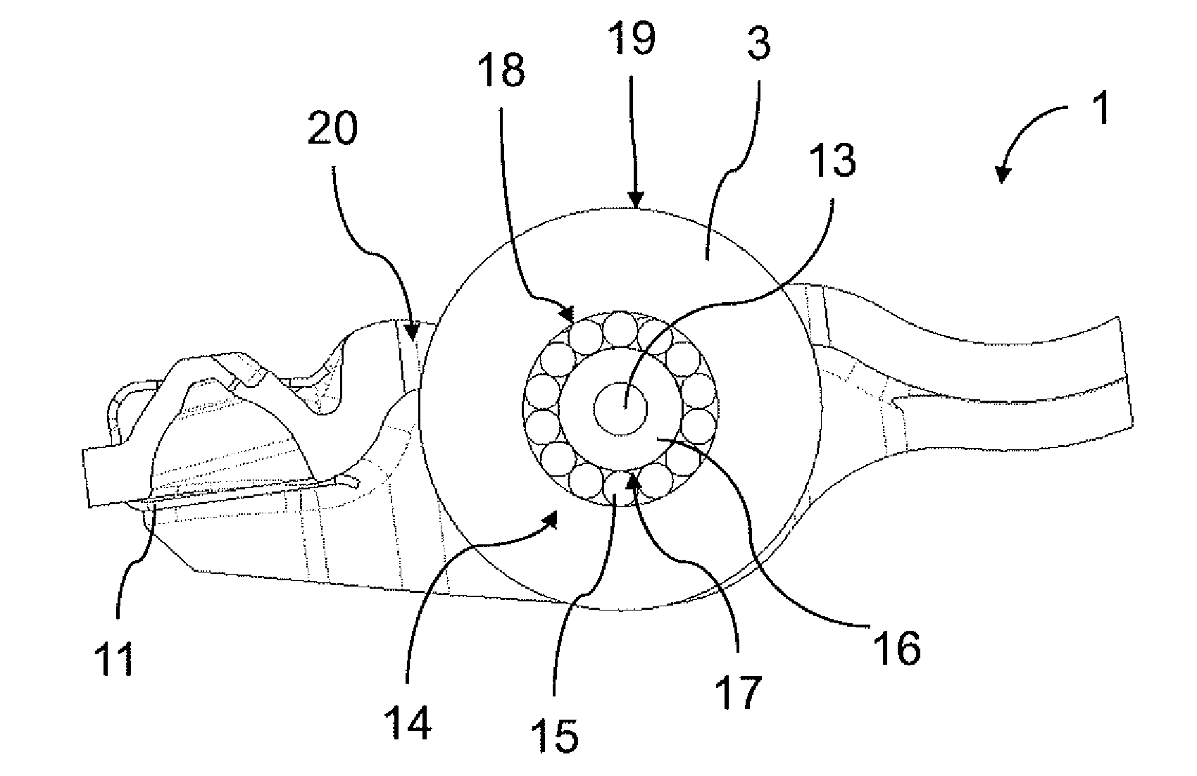
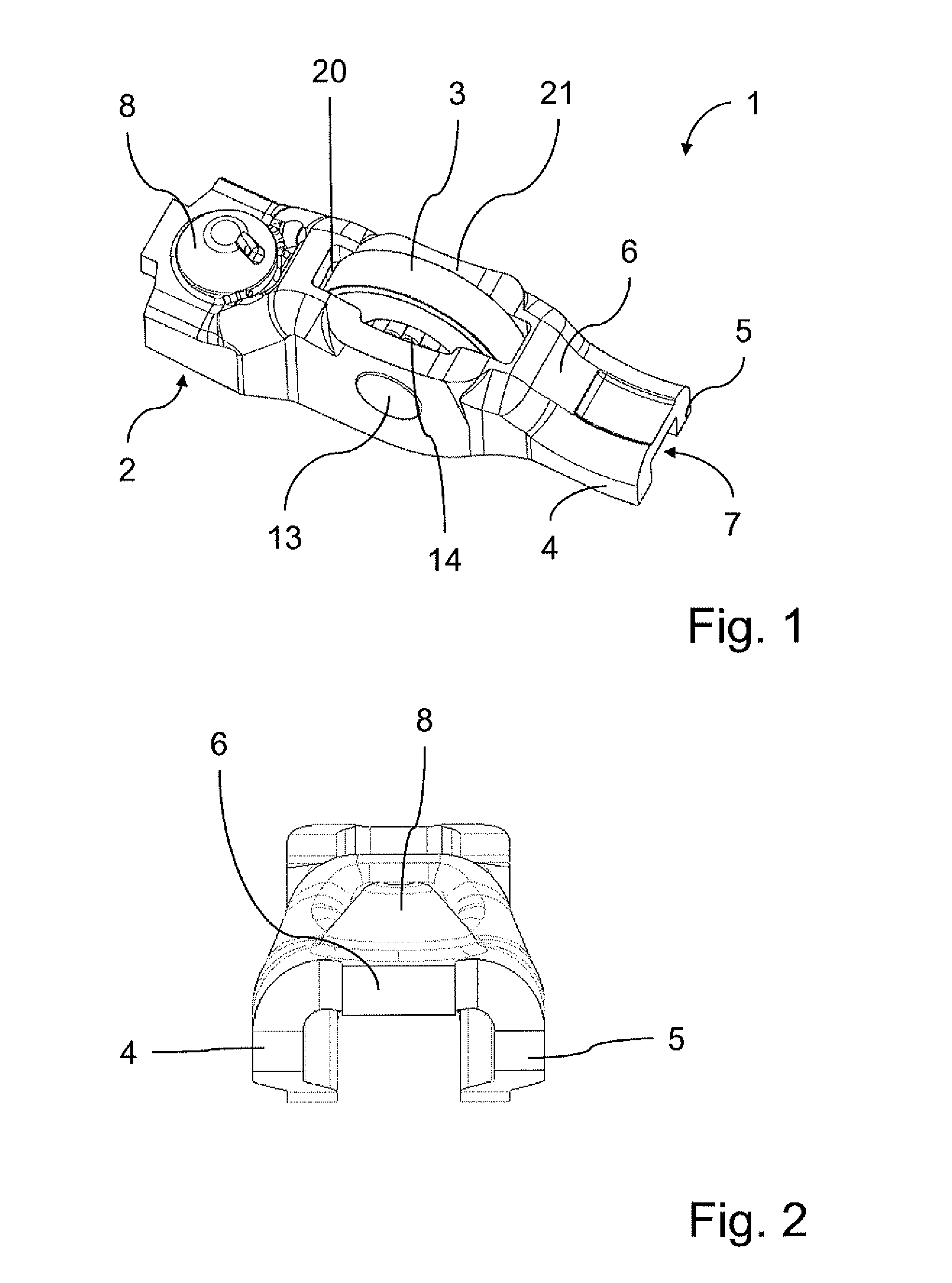
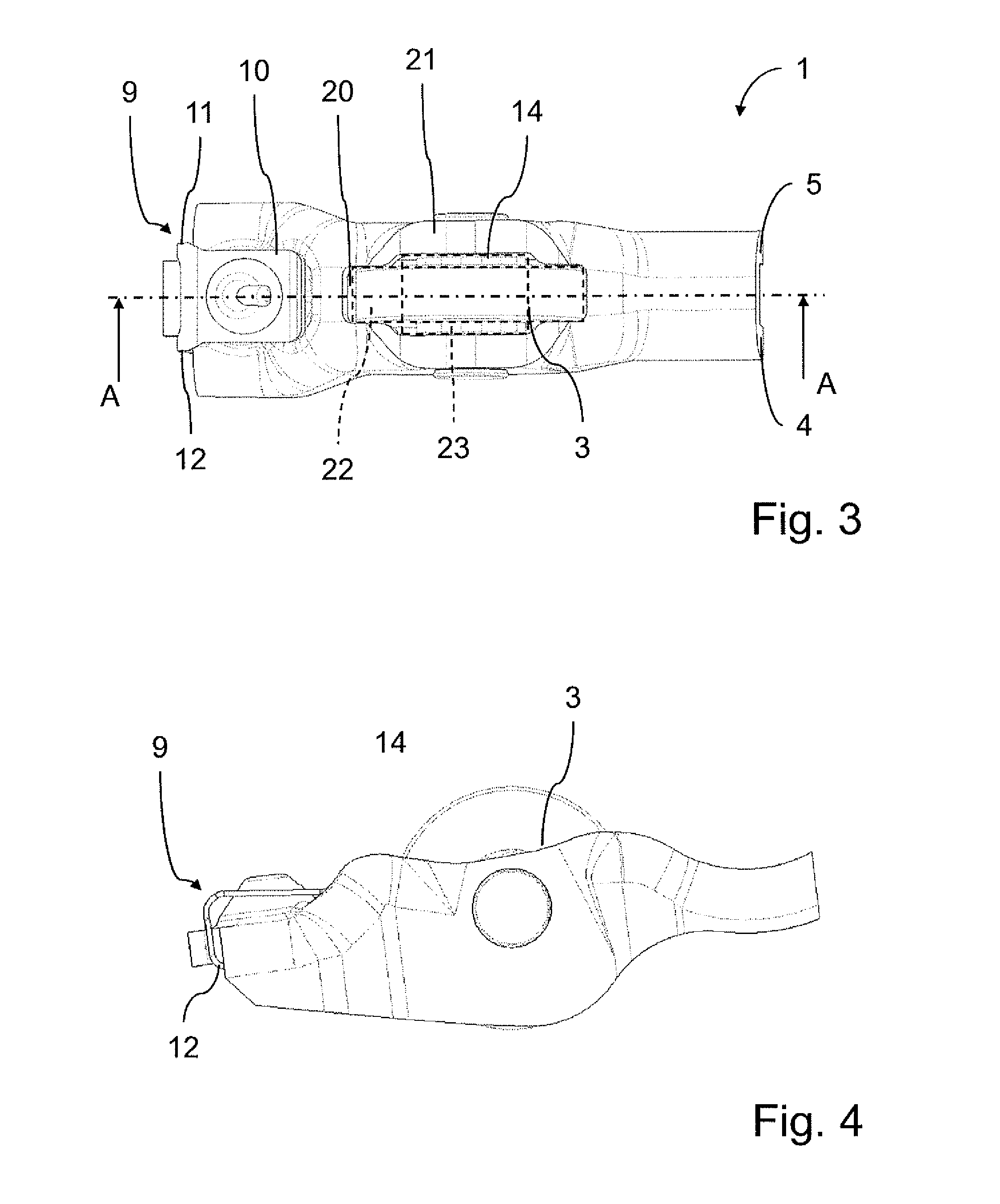
[0025]In FIGS. 1 to 5, 1 denotes a finger follower lever, which is comprised of a lever body 2 having a U-shaped profile and of a cam roller 3. The lever body 2 is formed by two parallel side walls 4 and 5, which are spaced apart, and by a transversely extending web 6, which connects the side walls 4 and 5, this being apparent especially from the front view in FIG. 2. In the region of a first end of the web 6, a valve actuating surface 7 is formed on an underside of the web 6, said underside being situated within the U-shaped profile of the lever body 2, by which valve actuating surface the lever body 2 rests on one end of a valve stem of an associated gas exchange valve in the installed state. In this region, the side walls 4 and 5 furthermore provide lateral guidance for the valve stem. At the opposite end of the web 6, in contrast, as is apparent from FIGS. 1 to 5, a joint socket 8 is formed in the web 6, by which socket a connection to a supporting element provided in a cylinder...


PUM


Abstract

A finger follower lever for actuating gas exchange valves of an internal combustion engine, having a lever body formed by two parallel side walls spaced apart by a transversely extending web. The web forms a first, joint socket end as a pivotable support for the lever, and a second end with a valve actuating surface. A cam roller is rotatably held between the side walls via a needle ring of a needle bearing. The cam roller projects partially via an aperture in the web for cam contact. The cam roller is narrow, and the needle ring projects beyond the cam roller at one axial end, and ends directly adjacent to a corresponding side wall. The aperture has a cross section defined by an overlap between a first, cam roller pocket with an extent corresponding to the cam roller in the axial direction, and a second pocket for the needle ring.

Description

CROSS-REFERENCE TO RELATED APPLICATIONS[0001]This application claims the benefit of German Patent Application No. 102011077024.0, filed Jun. 7, 2011, which is incorporated herein by reference as if fully set forth.FIELD OF THE INVENTION[0002]The invention relates to a finger follower lever for actuating a gas exchange valve of an internal combustion engine, having a lever body, which is formed by two parallel side walls, which are spaced apart, and by a transversely extending web, which connects the side walls, the web forming in the region of a first end a joint socket which serves to provide pivotable support for the lever body, and defining in the region of a second end a valve actuating surface provided for contact with the gas exchange valve, the side walls accommodating between them, in holes, an axle pin which guides a cam roller rotatably via a needle ring of a needle bearing, and the web defining a downwardly-open U-shaped profile of the lever body together with the side wa...

Claims


Application Information

Patent Timeline
IPC IPC(8): F01L1/18
CPCF01L1/185F01L2103/00F01L2105/00Y10T74/20882F01L2303/00F01L2305/00
Inventor MOCK, STEPHANVIERTEL, JOCHEN
Owner SCHAEFFLER TECH AG & CO KG
Why Eureka
Try Eureka