System and method for detecting, characterizing, and tracking an inductive power receiver

a technology of inductive power receiver and receiver, applied in the field of system and method for detecting, characterizing and tracking an inductive power receiver, can solve problems such as the field of persistence, and achieve the effect of coupling ratio and coupling ratio

Inactive Publication Date: 2012-12-13
ACCESS BUSINESS GRP INT LLC
View PDF15 Cites 102 Cited by
  • Summary
  • Abstract
  • Description
  • Claims
  • Application Information

AI Technical Summary

Benefits of technology

[0009]The position of an inductive power receiver can be determined by analyzing the magnitude of a characteristic of power in the one or more resonators. The magnitude of a characteristic of power is representative of the amount of flux penetrating the resonator from the inductive power receiver. Therefore, the closer the inductive power receiver is to a given resonator, the higher the magnitude.
[0011]The inductive charger can dynamically configure a plurality of inductors, sometimes referred to as coils, arranged in an array. Depending on how the system is configured, some inductors can be inductive power transmitters, some can be resonators, and some can be open circuit. In some embodiments, some inductors can be permanently configured as resonators or inductive power transmitters and other inductors can be dynamically configurable. By dynamically configuring the inductor array, an inductive power receiver can be quickly detected, characterized or tracked. In one embodiment, a multiplexer connects inductors to either a driver, a reference voltage, or leaves them disconnected as an open circuit. When an inductor is connected to the reference voltage, it becomes a resonator and when an inductor is connected to a driver, it becomes an inductive power transmitter.
[0012]Alternatively, the inductive charger may have a dedicated power transfer coil and use resonating coils to sense whether a remote device is properly aligned with the power transfer coil. The resonating coils may be constructed using low cost coils such as single conductor wire wound coils, surface mount inductors, or printed inductors made of PCB material. The inductive charger may use the device location information to adjust power transfer characteristics such as reducing the maximum allowable power when a device is misaligned. The inductive charger may also display information to a user about the current alignment of the remote device, such as an OLED display or simple LED array. The inductive charger may also provide alignment information to the remote device and the remote device may determine to display the alignment information to the user on a display system of the remote device. This information may be communicated through the coils as a modulated power signal, or may be communicated through an alternative data communication channel such as Bluetooth or WiFi.
[0014]In another alternative embodiment, two or more drivers are used so that multiple inductive power receivers can receive power simultaneously. To configure coils in the array as resonating coils, one field effect transistor of the driver is turned on and left on, to connect the coil to a reference voltage. This allows the coils to be resonating coils, but also allows multiple devices to be powered separately since two or more drivers can be connected to a fully selectable array.

Problems solved by technology

However, when a piece of metal is placed proximate to the inductive charging surface, the induced currents in the metal do not perpetuate the field to the resonator.

Method used


Image

  • System and method for detecting, characterizing, and tracking an inductive power receiver
  • System and method for detecting, characterizing, and tracking an inductive power receiver
  • System and method for detecting, characterizing, and tracking an inductive power receiver

Examples


Embodiment Construction

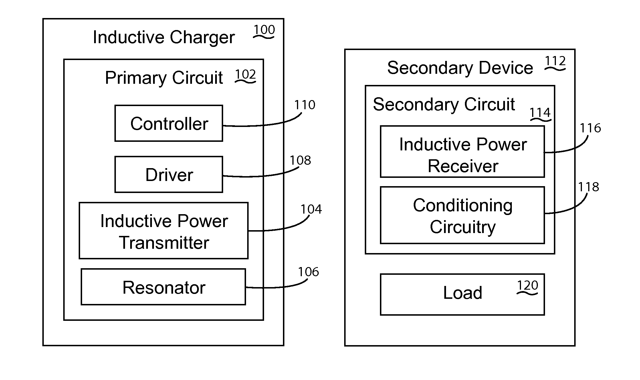
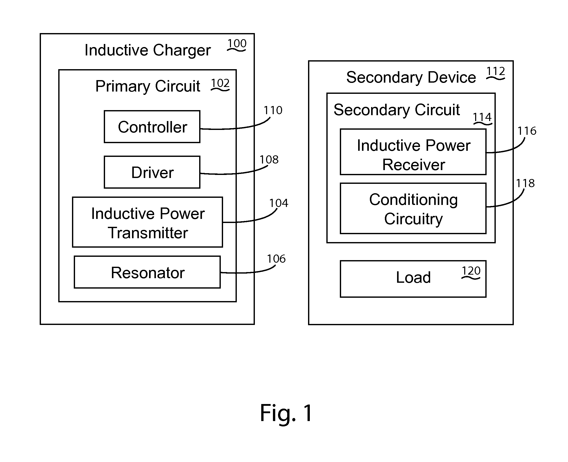
[0037]An inductive charging system in accordance with an embodiment of the present invention is shown in FIG. 1. The inductive charging system includes an inductive charger 100 that generates an electromagnetic field to wirelessly transfer power to a secondary device. The inductive charger can include various primary circuitry 102, which will be discussed in more detail below. In general, the primary circuitry can include one or more inductive power transmitters 104, one or more resonators 106, a driver 108 for energizing one or more inductive power transmitters 104, one or more sensors (not shown), and a controller 110. The secondary device 112 can include a load and various secondary circuitry 114, which will also be discussed in more detail below. Examples of secondary devices can include mobile telephones, tablets, laptops, or any other device desiring power. In general, the secondary circuitry 114 can include one or more inductive power receivers 116, a load 120, and circuitry ...


PUM


Abstract

A system and method for detecting, characterizing, and tracking an inductive power receiver proximate to an inductive charging surface of an inductive charger. One or more resonators and one or more sensors provide information that can be utilized to detect, characterize, and track the inductive power receiver. The resonators can be configured to determine position of a remote device using magnitude or phase of sensors associated with resonators. In addition, by monitoring the inductive power transmitter and the resonators, the charger can differentiate between whether parasitic metal is present, a remote device is present, or both are present.

Description

BACKGROUND OF THE INVENTION[0001]An inductive power supply, sometimes referred to as an inductive charger, may be used to supply wireless power to power or charge secondary devices. In some known inductive power supplies, secondary devices are powered or charged by placing them on a charging surface. Some inductive power supplies limit spatial freedom by requiring specific placement and orientation of the remote device with respect to the inductive power supply.[0002]In some known inductive power supply systems, a single primary coil is embedded in a charging surface of a charging device and a single secondary coil is embedded in a secondary device. Power can be provided from a mains input to the charging device, sometimes referred to as a wireless power supply. Assuming the mains input provides AC power, the power can be rectified in a mains rectification circuit into DC power and then can be adjusted in a DC / DC power supply. An inverter can switch the DC power at a frequency contr...

Claims


Application Information

Patent Timeline
Patent Type & Authority Applications(United States)
IPC IPC(8): H02J7/00
CPCH04B5/0037H02J7/025H02J50/90H02J50/402H02J50/12H02J7/00034H02J50/70H04B5/0075H02J7/00
Inventor MOES, BENJAMIN C.BAARMAN, DAVID W.
Owner ACCESS BUSINESS GRP INT LLC
Why Eureka
Try Eureka