
Diffuse reflection output conversion method, attached powder amount conversion method, and image forming apparatus

a technology of diffuse reflection and output conversion method, which is applied in the direction of electrographic process, electrographic process apparatus, instruments, etc., can solve the problem that the output of diffuse reflection cannot be calibrated accurately

Inactive Publication Date: 2012-12-13
RICOH KK
View PDF6 Cites 7 Cited by
  • Summary
  • Abstract
  • Description
  • Claims
  • Application Information

AI Technical Summary

Benefits of technology

The present invention provides a method for detecting the amount of powder attached to a surface using diffuse reflection of light. The method involves using an optical detector to detect both specular and diffuse reflections of light from gradation patterns on the surface. The amount of powder attached to the gradation patterns is determined based on the ratio of diffuse reflection output to a calibration coefficient obtained from a diffuse reflection output conversion value. The invention also provides an image forming apparatus that includes the diffuse reflection output conversion method. The technical effect of the invention is to provide a more accurate and reliable method for detecting the amount of powder attached to a surface, which can be useful in various applications such as quality control in manufacturing processes.

Problems solved by technology

Therefore, the diffuse reflection output cannot be calibrated accurately.

Method used


Image

  • Diffuse reflection output conversion method, attached powder amount conversion method, and image forming apparatus
  • Diffuse reflection output conversion method, attached powder amount conversion method, and image forming apparatus
  • Diffuse reflection output conversion method, attached powder amount conversion method, and image forming apparatus

Examples


Embodiment Construction

[0041]An embodiment according to the present invention will now be explained with reference to some drawings.

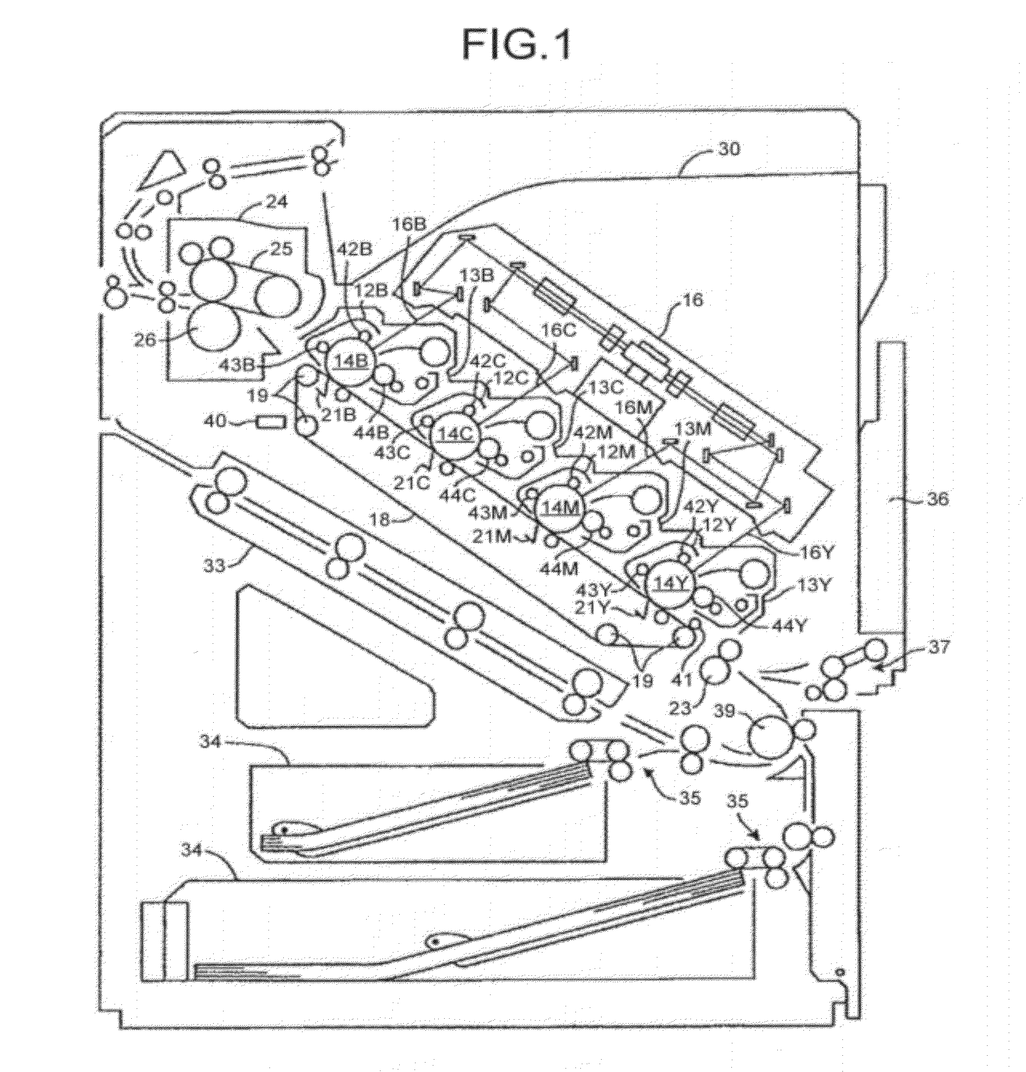
[0042]To begin with, a general structure of a direct transfer, four-drum tandem type color printer that is an image forming apparatus according to the embodiment will now be explained with reference to FIG. 1.

[0043]The color laser printer includes three paper feed trays, a bypass tray 36 and two paper feeding cassettes 34 (first paper feed tray) and 34 (second paper feed tray). Paper feeding rollers 37 separate transfer paper, being sheet-like recording media not illustrated, fed from the bypass tray 36 sequentially from the one at the top, and conveys the transfer paper thus separated into a registration roller pair 23.

[0044]Paper feeding rollers 35 separate transfer paper fed from the first paper feed tray 34 or the second paper feed tray 34, sequentially from the one at the top, and the transfer paper is then conveyed into the registration roller pair 23 via a pair of carr...


PUM


Abstract

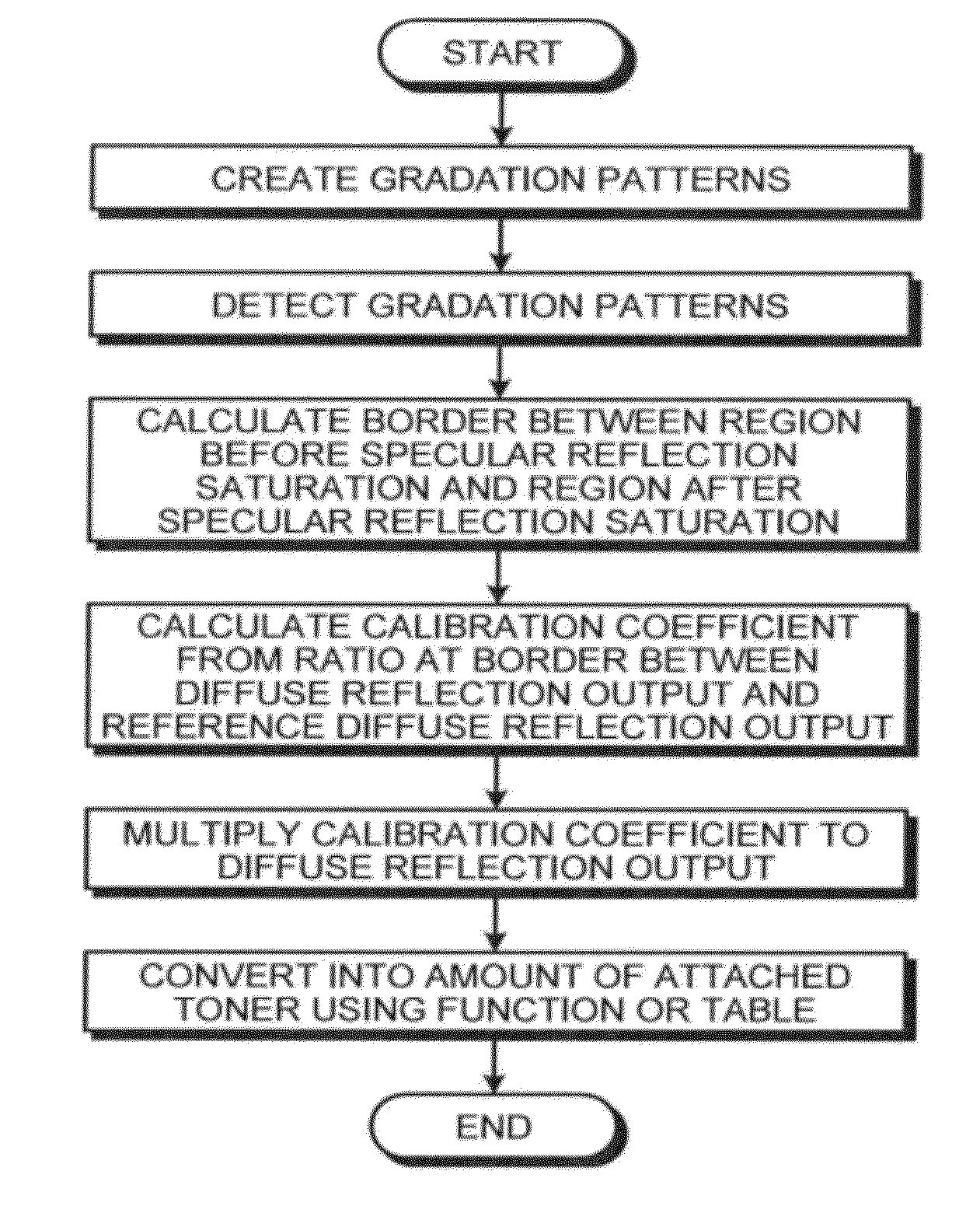
In an embodiment, a diffuse reflection output conversion method is executed in an apparatus detecting a plurality of gradation patterns. The apparatus includes a light emitter and light receiver, and detects specular reflection and diffuse reflection simultaneously. A region before specular reflection saturation is a region where the specular reflection component decreases and saturates at minimum level. A diffuse reflection detector is calibrated by: obtaining a diffuse reflection output resulting from an amount of attached powder at a border between the region before specular reflection saturation and the region after specular reflection saturation; calculating a ratio between the diffuse reflection output and a reference diffuse reflection output calculated in advance as a calibration coefficient; and multiplying a diffuse reflection output obtained from the gradation patterns by the calibration coefficient calculated at the calculating.

Description

CROSS-REFERENCE TO RELATED APPLICATIONS[0001]The present application claims priority to and incorporates by reference the entire contents of Japanese Patent Application No. 2011-131461 filed in Japan on Jun. 13, 2011.BACKGROUND OF THE INVENTION[0002]1. Field of the Invention[0003]The present invention relates to a diffuse reflection output conversion method used in detecting the amount of attached powder, such as toner, an attached powder amount conversion method using the diffuse reflection output conversion method, and an image forming apparatus such as a copier, a printer, a facsimile, a plotter, and a multi-function peripheral (MFP) having at least one of these functions, including a function executing these methods.[0004]2. Description of the Related Art[0005]To achieve a stable image density in a conventional electrophotographic image forming apparatus, such as a copier and a laser beam printer, toner patches (gradation patterns) for detecting density are formed on an image ca...

Claims


Application Information

Patent Timeline
Patent Type & Authority Applications(United States)
IPC IPC(8): G03G15/00G01B11/24
CPCG01N21/4738G03G2215/0148G03G15/5058G01N21/4785
Inventor MUROI, HIDEOHIRAYAMA, YUSHIHIRAI, SHUJIISHIBASHI, HITOSHI
Owner RICOH KK
Learn More