LED light distribution lens, LED lighting module having LED light distribustion lens and lighting equipment having LED lighting module

a technology of led lighting and distribution lens, which is applied in the direction of lighting support devices, lighting and heating apparatus, instruments, etc., to achieve the effects of reducing production costs, improving light extraction efficiency, and reducing the cost of producing molds for light emitting surfaces

Inactive Publication Date: 2011-04-28
ENDO LIGHTING CORP
View PDF8 Cites 46 Cited by
  • Summary
  • Abstract
  • Description
  • Claims
  • Application Information

AI Technical Summary

Benefits of technology

[0024]According to the present invention, the designed light distribution can be achieved, the diffuse reflection and unintended diffusion cannot be caused, and the l...

Problems solved by technology

However, the prior LED light, distributio...

Method used


Image

  • LED light distribution lens, LED lighting module having LED light distribustion lens and lighting equipment having LED lighting module
  • LED light distribution lens, LED lighting module having LED light distribustion lens and lighting equipment having LED lighting module
  • LED light distribution lens, LED lighting module having LED light distribustion lens and lighting equipment having LED lighting module

Examples


Embodiment Construction

[0034]Now an embodiment of the present invention is explained based on FIG. 1-FIG. 8.

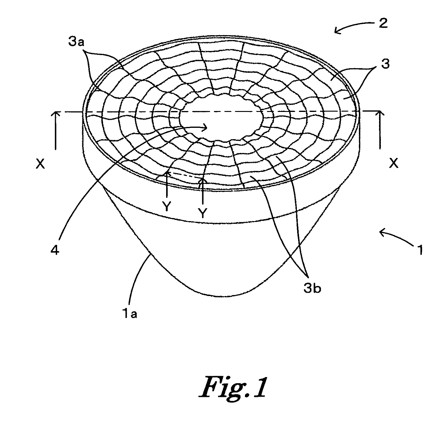
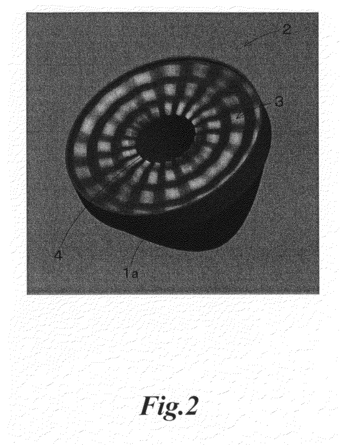
[0035]Lines such as 3a, 3b are indicated on a light emitting surface 2, which are mentioned hereinafter, in FIG. 1 and FIG. 5, however, they are not actually formed on the light emitting surface 2 and they are only shown for representation and explanation of the configuration (concave-convex surface) of the light emitting surface 2. FIG. 2 is a 3D image showing the LED light distribution lens of the present invention.

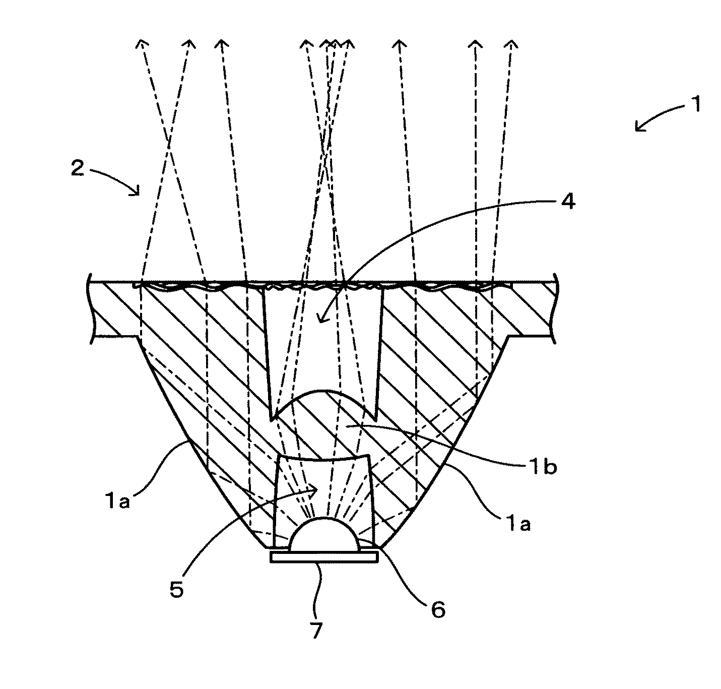
[0036]An LED light distribution lens 1 is made of a transparent acrylic material and the like and is formed like a mortar of conic shape of which circular portion is formed upward, as shown in FIG. 1 and FIG. 2.

[0037]The upper face of the LED light distribution lens 1 has the light emitting surface 2 which is circular in plan view and emits the light from an LED 6 forward. The light emitting surface 2 is formed with a continuous surface in a manner such that a plurality of convex surfac...


PUM


Abstract

LED light distribution lens having a light emitting surface whose shape is circular in its plan view, which emits forward light from LED disposed in its center.
The LED light distribution lens is characterized by the construction of the emitting surface which is low at production cost and so designed as not to cause the diffuse reflection and unintended diffusion. Such emitting surface has a plural convex surfaces formed both in its radial and its circumferential directions in a manner that the convex surfaces surround the circumference of the LED and has continuous surfaces formed such that the boundary portions of the convex surfaces constitute the concave surfaces, thereby realizing expected light distribution based on design specification.

Description

TECHNICAL FIELD[0001]The present invention relates to an LED light distribution lens, an LED lighting module having the LED light distribution lens and lighting equipment having the LED lighting module.BACKGROUND ART[0002]Lighting equipment using an LED has been widely used as a light source with long life and low power consumption in these days. An LED distribution lens for use in such lighting equipment has been produced with many efforts in order to emit forward the light of LED efficiently.[0003]FIG. 8 shows an example of an LED distribution lens for use in lighting equipment using an LED as a light source.[0004]An LED distribution lens 100 in the figure has a light emitting surface 200 having a plurality of honeycomb cells 300 and the surface of the cell 300 is processed to be a convex shape so as to emit the light passing therethrough into a predetermined direction.[0005]The following patent citation 1 describes an LED distribution lens having a central prism formed in the cen...

Claims


Application Information

Patent Timeline
IPC IPC(8): F21V5/04H01L33/58G02B17/00
CPCF21S8/04F21V5/04F21V7/0091G02B19/0061F21Y2101/02G02B19/0028F21V21/30F21Y2115/10
Inventor SHIMOKAWA, TEPPEI
Owner ENDO LIGHTING CORP
Why Eureka
Try Eureka