Autonomous cleaning device

a cleaning device and autonomous technology, applied in the direction of carpet cleaners, electric equipment installation, applications, etc., can solve the problems of lowering cleaning performance, abnormal noise generation, and the distance between the blade and the floor is not adjusted, so as to improve the dust suction performance

Active Publication Date: 2012-12-20
SAMSUNG ELECTRONICS CO LTD
View PDF3 Cites 59 Cited by
  • Summary
  • Abstract
  • Description
  • Claims
  • Application Information

AI Technical Summary

Benefits of technology

[0008]It is an aspect to provide an autonomous cleaning device having improved dust suction performance.
[0009]It is another aspect to provide an autonomous cleaning device that secures travel performance and cleaning performance irrespective of a floor state.
[0011]In accordance with one aspect, an autonomous cleaning device includes a main body having an opening, a brush unit rotatably provided in the opening of the main body, and a blade assembly to guide introduction of dust swept up by the brush unit, wherein the blade assembly includes a blade having a first part fixed to the main body and a second part extended from the first part toward a floor and a support member provided at a rear of the blade in a travel direction of the main body to prevent the second part of the blade from being bent in a direction opposite to the travel direction of the main body.
[0036]In accordance with another aspect, an autonomous cleaning device includes a main body having an opening, a brush unit rotatably provided in the opening of the main body, and a blade to guide movement of dust swept up by the brush unit, wherein the blade includes a first contact portion formed at the front of the end of the blade in a direction of travel so that the first contact portion protrudes downward and a second contact portion provided at the rear of the first contact portion in the direction of travel so that the second contact portion is disposed in a longitudinal direction of the blade to support the first contact portion so that the first contact portion does not fall into valleys of a rugged floor.
[0037]In accordance with a further aspect, an autonomous cleaning device includes a main body having an opening, a brush unit rotatably provided in the opening of the main body, and a blade assembly to guide movement of dust swept up by the brush unit, wherein the blade assembly includes a blade having a first part fixed to the main body and a second part extended from the first part toward a floor, a fixing member disposed above the blade to push at least a portion of the second part of the blade so that an end of the second part of the blade remains in tight contact with the floor, and a support member provided at a rear of the blade in a travel direction of the main body to prevent the second part of the blade from being bent in a direction opposite to the travel direction of the main body.
[0038]The fixing member and the support member may restrict movement of the second part of the blade to within a predetermined range.

Problems solved by technology

However, the distance between the blade and a floor is not adjusted.
When the blade moves off of the floor, the dust is not properly guided, thereby lowering cleaning performance.
When the blade comes into excessively tight contact with the floor, abnormal noise is generated.

Method used


Image

  • Autonomous cleaning device
  • Autonomous cleaning device
  • Autonomous cleaning device

Examples


Embodiment Construction

[0054]Reference will now be made in detail to the embodiments, examples of which are illustrated in the accompanying drawings, wherein like reference numerals refer to like elements throughout.

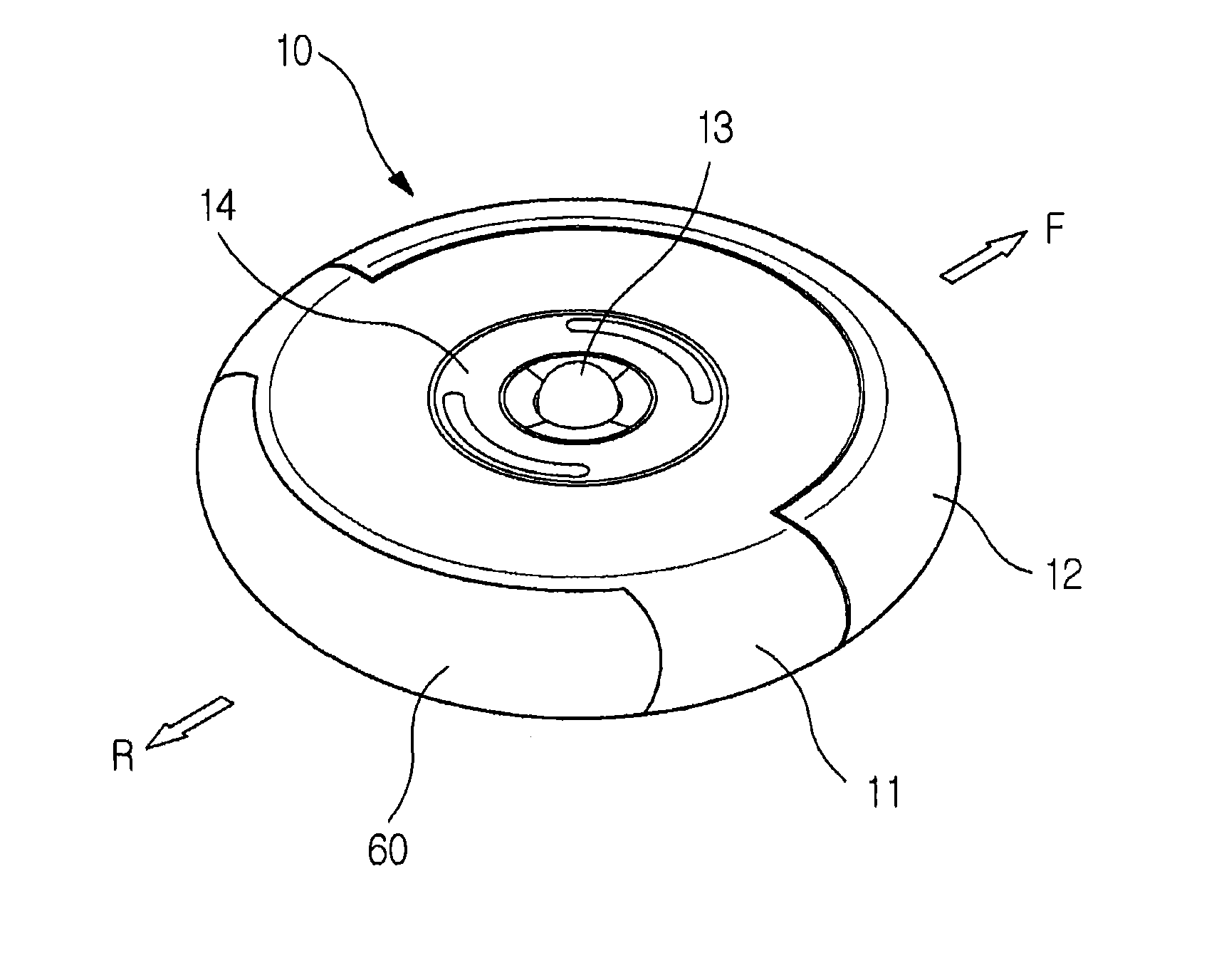
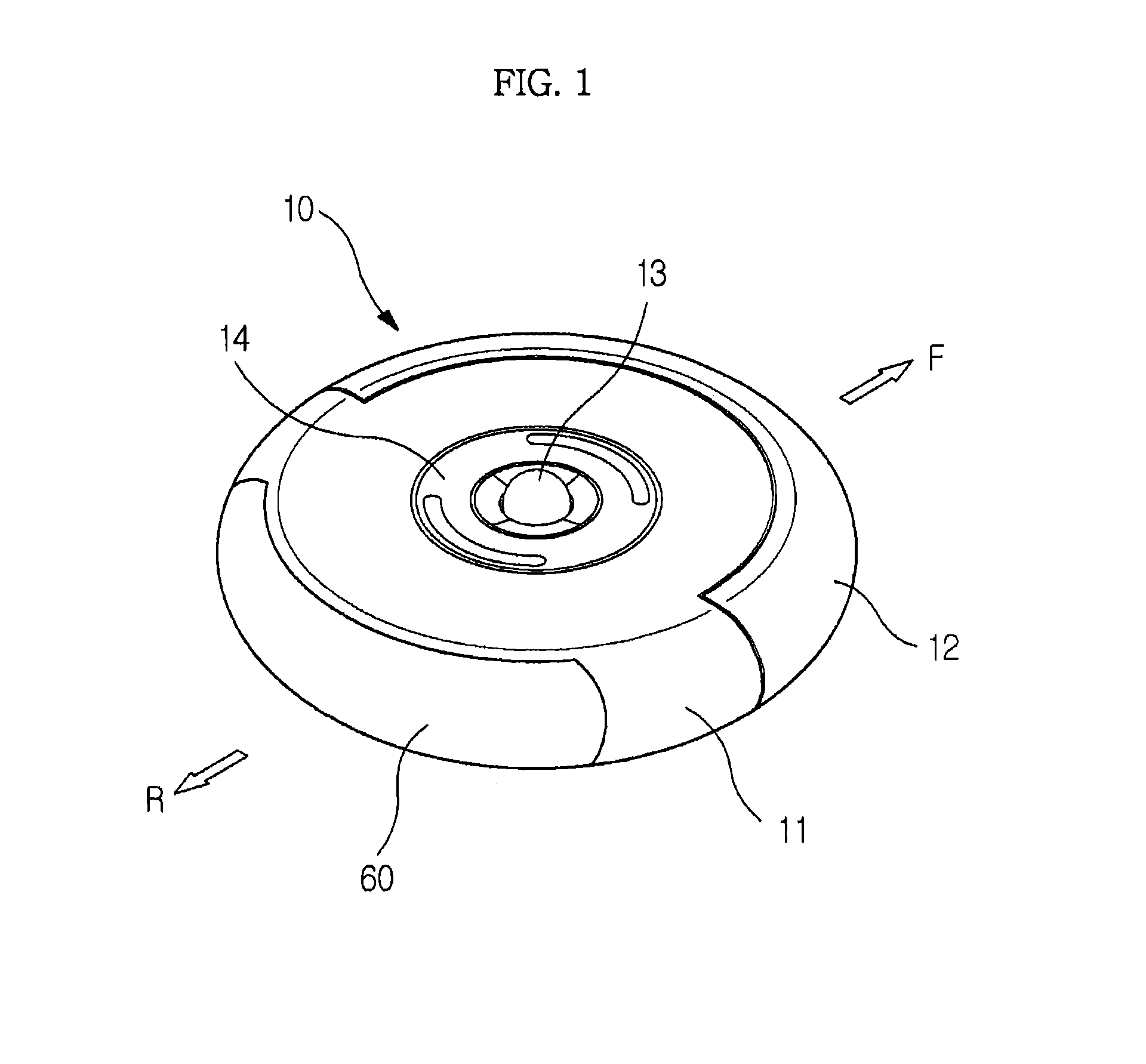
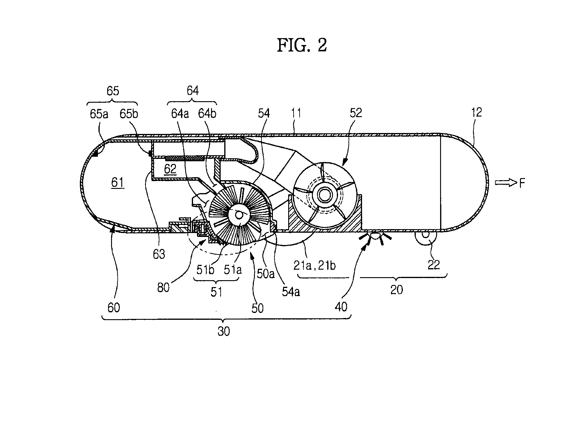
[0055]FIG. 1 is a perspective view illustrating an autonomous cleaning device according to an embodiment, FIG. 2 is a sectional view illustrating the autonomous cleaning device according to the embodiment, and FIG. 3 is a bottom perspective view illustrating the autonomous cleaning device according to the embodiment.

[0056]As shown in FIGS. 1 to 3, an autonomous cleaning device 10 may include a main body 11, a drive unit 20, a cleaning unit 30 and a controller (not shown).

[0057]The main body 11 may be configured in various forms. For example, the main body 11 may be configured in a circular form. The circular main body 11 has a uniform radius of rotation, and therefore, the main body 11 may avoid contact with surrounding obstacles and may easily change course. Also, during travel, the main body...


PUM


Abstract

A blade assembly of an autonomous cleaning device. The blade assembly includes a blade having a first part fixed to the main body and a second part extended from the first part toward a floor and a support member having at least a portion disposed adjacent to the second part of the blade to restrict movement of the second part of the blade to within a predetermined range.

Description

CROSS-REFERENCE TO RELATED APPLICATION[0001]This application is a divisional of U.S. application Ser. No. 13,279,892 filed Oct. 24, 2011, which claims the priority benefit of Korean Patent Application No. 2010-0103778 and No. 2011-0086080, filed on Oct. 25, 2010 and Aug. 26, 2011 in the Korean Intellectual Property Office, the disclosure of which is incorporated herein by reference.BACKGROUND[0002]1. Field[0003]Embodiments relate to an autonomous cleaning device wherein the structure of a blade assembly is improved, thereby improving cleaning efficiency.[0004]2. Description of the Related Art[0005]An autonomous mobile robot is a device that travels about an arbitrary area to perform a predetermined task without user manipulation. The robot may travel autonomously to a considerable extent, and autonomous travel may be embodied in various manners. For example, the robot may travel along a predetermined route using a map or may travel using a sensor to sense surroundings thereof withou...

Claims


Application Information

Patent Timeline
Patent Type & Authority Applications(United States)
IPC IPC(8): A47L11/00
CPCA47L9/0411A47L9/0466A47L9/0633A47L9/0626A47L11/4052A47L2201/00A47L11/4044A47L9/02A47L9/04A47L9/28A47L11/20
Inventor JUNG, HYUN SOOHAN, SEUNG ILKIM, DONG WONKIM, BO SANGLEE, JUN HWA
Owner SAMSUNG ELECTRONICS CO LTD
Why Eureka
Try Eureka