
Substrate processing method and substrate processing unit

Active Publication Date: 2012-12-20
EBARA CORP
View PDF3 Cites 10 Cited by
  • Summary
  • Abstract
  • Description
  • Claims
  • Application Information

AI Technical Summary

Benefits of technology

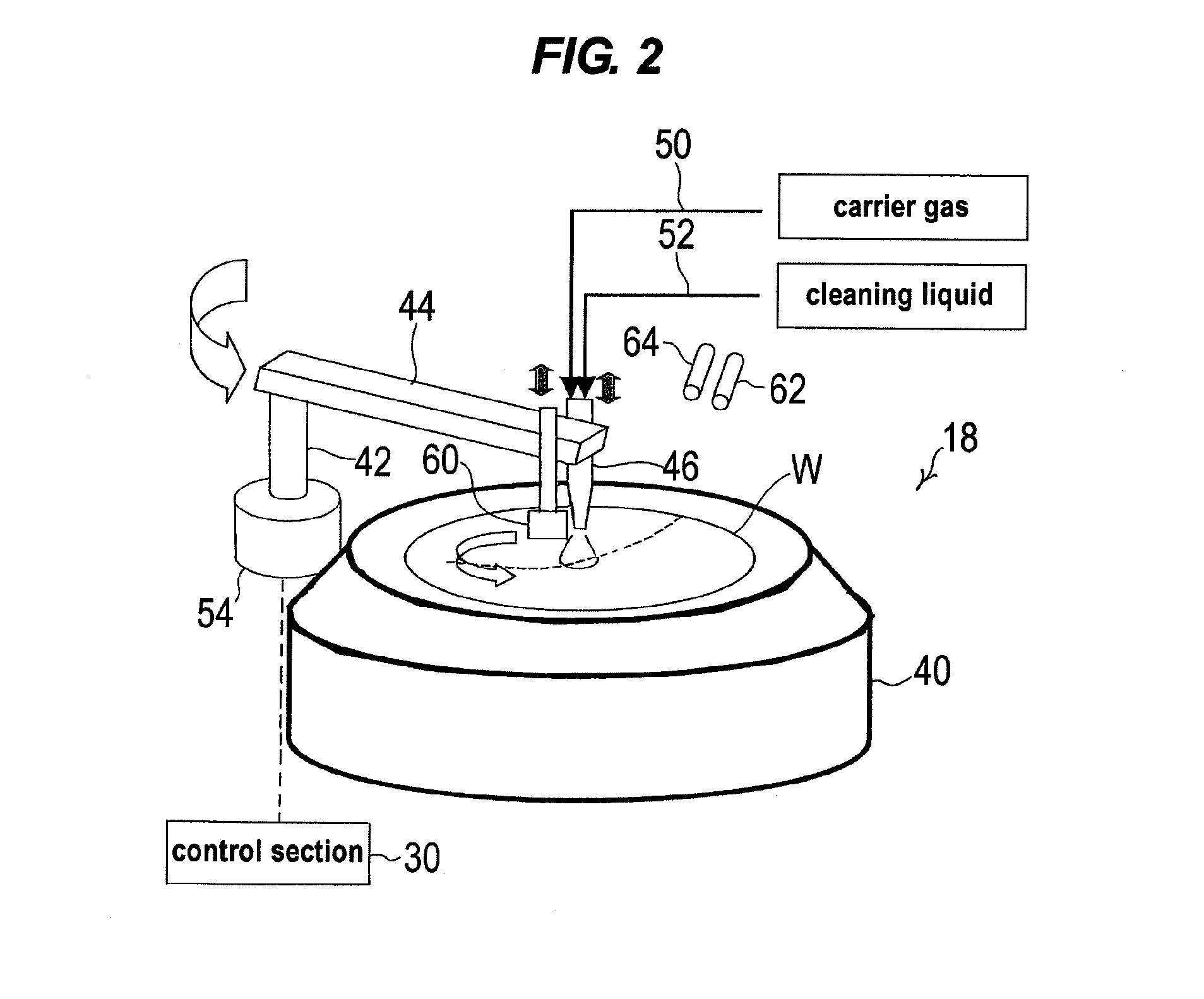
[0012]The present invention has been made in view of the above situation in the background art. It is therefore an object of the present invention to provide a substrate processing method and a substrate processing unit which can easily and optimally control the movement speed of a fluid nozzle while taking account of the relationship with factors such as processing time (throughput), making it possible to perform processing, such as cleaning or drying, of a substrate surface uniformly over the entire surface.
[0018]When there is a limit to the processing time (throughput), the power index α, and thus the movement speed V(r) of the fluid nozzle may be determined based on an allowed processing time. This makes it possible to perform processing of a substrate surface uniformly over the entire surface while responding to the request for the processing time.
[0023]Upon processing of a substrate, the movement speed V(r) of the fluid nozzle when it passes a position corresponding to a position on the substrate surface at a distance “r” from the center of the substrate can be easily determined by inputting the initial movement speed of the fluid nozzle and an allowed processing time necessary for the fluid nozzle to move from a processing start position to a processing end position.
[0024]According to the present invention, the movement speed V(r) of the fluid nozzle when it passes a position corresponding to a position on a substrate surface at a distance “r” from the center of the substrate can be determined by arbitrarily setting the power index α, e.g., based on an intended processing time (throughput). This makes it possible to perform processing of a substrate surface uniformly over the entire surface while responding to the request for the processing time.

Problems solved by technology

This sometimes involves discontinuity in the movement speed of the fluid nozzle, which may result in uneven drying of a substrate surface.
The proposed method, however, does not take account of the relationship between factors such as processing time (throughput) and the movement speed of a fluid nozzle such as a cleaning nozzle.

Method used


Image

  • Substrate processing method and substrate processing unit
  • Substrate processing method and substrate processing unit
  • Substrate processing method and substrate processing unit

Examples


Embodiment Construction

[0040]Preferred embodiments of the present invention will now be described with reference to the drawings.

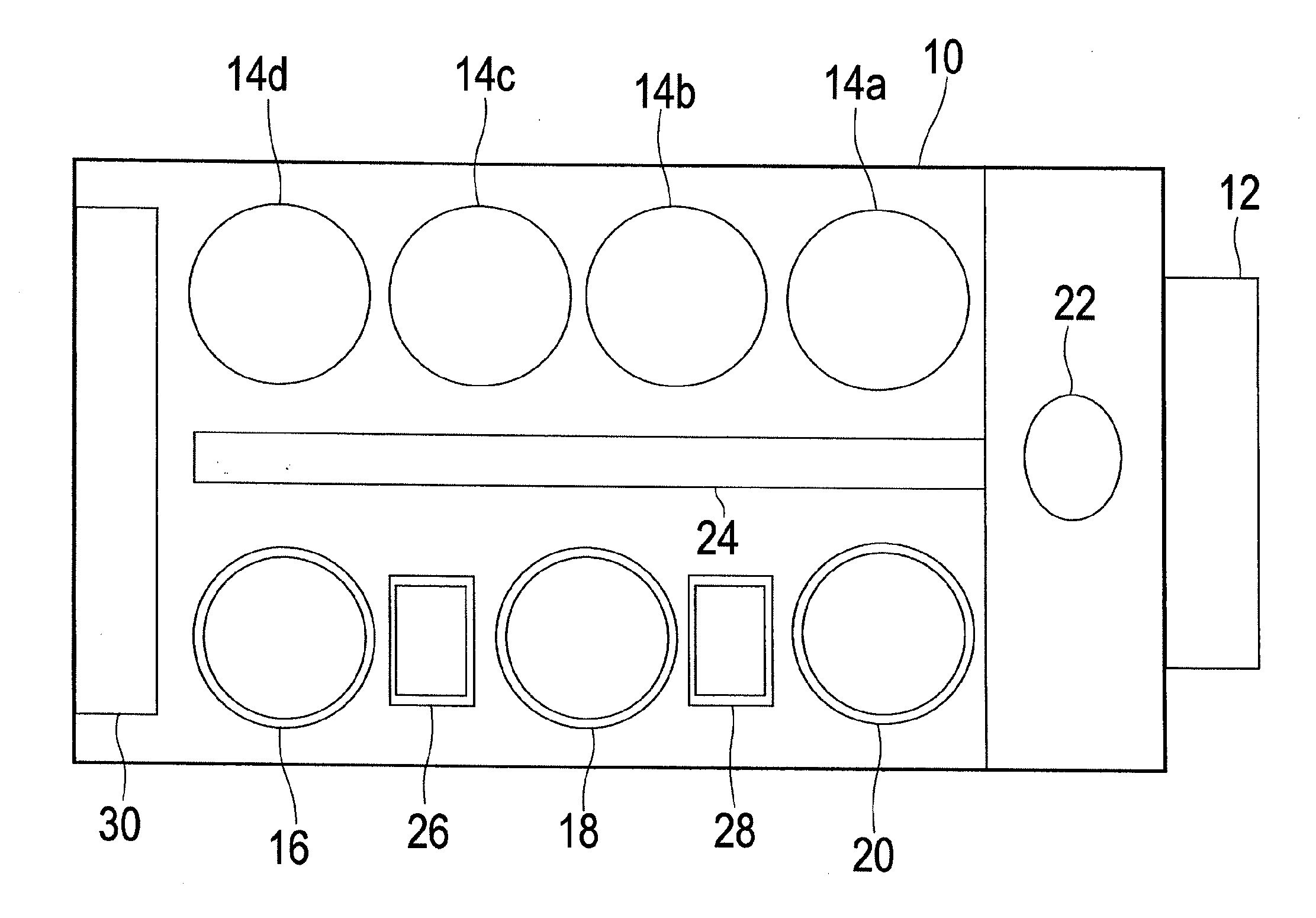
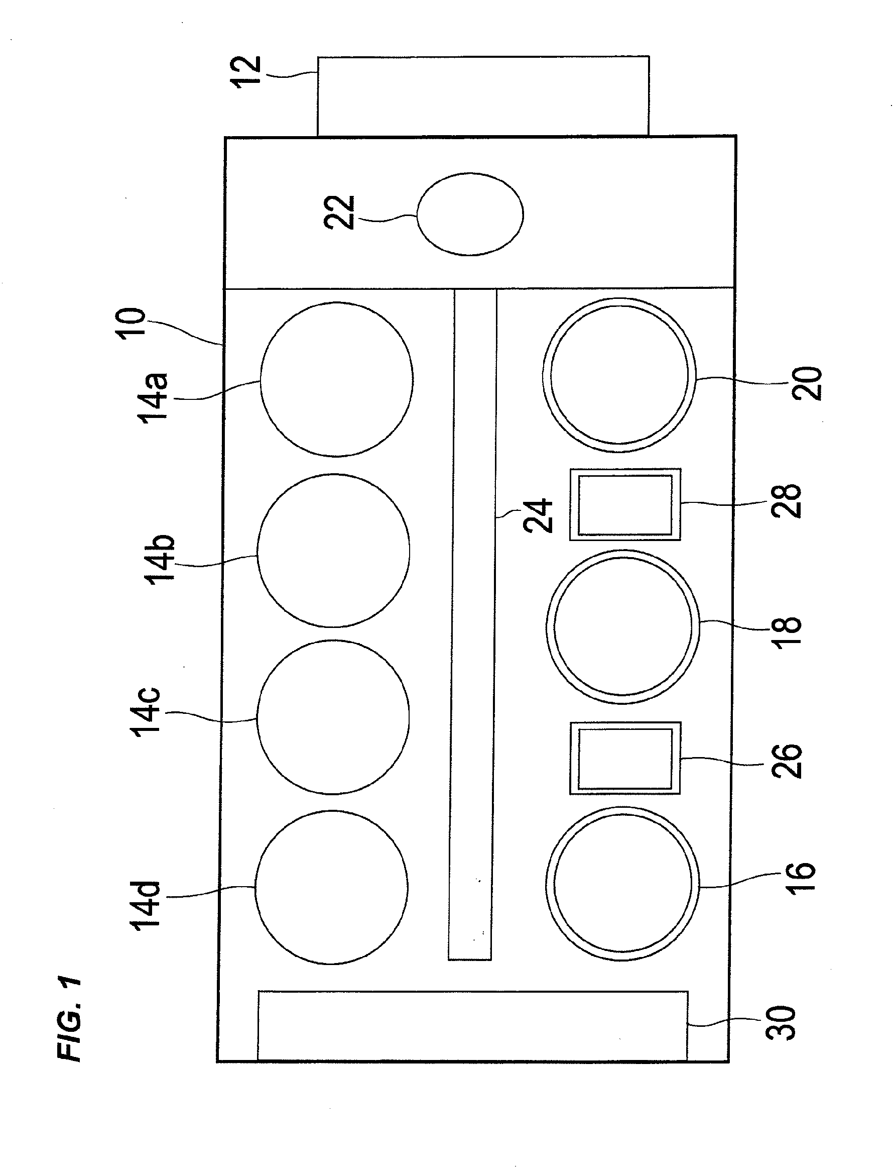
[0041]FIG. 1 is a plan view showing the overall construction of a substrate processing apparatus incorporating a substrate processing unit according to an embodiment of the present invention. As shown in FIG. 1, this substrate processing apparatus includes a generally-rectangular housing 10, and a loading port 12 for placing thereon a substrate cassette for storing a large number of substrates, such as semiconductor wafers. The loading port 12 is disposed adjacent to the housing 10 and can be mounted with an open cassette, a SMIF (standard manufacturing interface) or a FOUP (front opening unified pod). A SMIF and a FOUP are each an airtight container which houses therein a substrate cassette and which, by covering it with a partition wall, can keep the internal environment independent of the external environment.

[0042]In the housing 10 are housed four polishing units 14a-14d, a ...


PUM


Abstract

A substrate processing method includes jetting at least one fluid from a fluid nozzle toward a rotating substrate surface while moving the fluid nozzle from a center toward a periphery of the rotating substrate. The fluid nozzle is moved from the center of the substrate to a predetermined point at a constant initial movement speed. The fluid nozzle is subsequently moved from the predetermined point at a movement speed V(r) which satisfies the following relational expression: V(r)×rα=C (constant), where V(r) represents the movement speed of the fluid nozzle when it passes a position corresponding to a position on the substrate surface at a distance “r” from the center of the substrate, and α represents a power index.

Description

CROSS REFERENCE TO RELATED APPLICATIONS[0001]This document claims priority to Japanese Application Number 2011-133842, filed Jun. 16, 2011, the entire contents of which are hereby incorporated by reference.BACKGROUND OF THE INVENTION[0002]1. Field of the Invention[0003]The present invention relates to a substrate processing method and a substrate processing unit, and more particularly to a substrate processing method and a substrate processing unit which are used to carry out processing, such as cleaning or drying, a surface of a substrate, such as a semiconductor wafer, in a contactless manner.[0004]2. Description of the Related Art[0005]A two-fluid jet (2FJ) cleaning method is known as a cleaning method for cleaning a substrate surface in a contactless manner. This cleaning method involves jetting a high-speed gas containing fine liquid droplets (mist) from a two-fluid nozzle toward a substrate surface and causing the fine liquid droplets to collide against the substrate surface. ...

Claims


Application Information

Patent Timeline
IPC IPC(8): B08B3/02B08B3/04
CPCB08B3/024H01L21/67051H01L21/302
Inventor WANG, XINMINGMIYAZAKI, MITSURUMATSUSHITA, KUNIMASA
Owner EBARA CORP
Learn More