Methods for forming piezoelectric ultrasonic transducers, and associated apparatuses

a piezoelectric ultrasonic transducer and ultrasonic technology, applied in piezoelectric/electrostrictive/magnetostrictive devices, piezoelectric/electrostriction/magnetostriction machines, mechanical vibration separation, etc., can solve the problem of poor or inconsistent electrically-conductive engagement between the first/bottom electrode and the conformal metal layer, and the inability to form vias according to these exemplary prior art methods. , to achieve the effect o

Active Publication Date: 2012-12-20
RES TRIANGLE INST
View PDF2 Cites 89 Cited by
  • Summary
  • Abstract
  • Description
  • Claims
  • Application Information

AI Technical Summary

Problems solved by technology

However, the formation of such vias (i.e., by etching) according to these exemplary prior art methods may be difficult due to, for example, the first / bottom electrode and / or the dielectric film being relatively thin, and thus providing an insufficient etch stop layer.
However, such electrically-conductive connections may, in some instances, implement a lesser desirable conductor (i.e., doped silicon) connecting the first / bottom electrode to the conformal metal layer deposited in the via.
In such instances, it may be difficult to connect the conformal metal layer to the metal extending to the first / bottom electrode, since the sidewalls and / or corners of the vias may be rough or incompletely etched, thus possibly resulting in poor or inconsistent electrically-conductive engagement between the first / bottom electrode and the conformal metal layer.
In such instances, mechanical flexure of the actuated pMUT device may initiate or accelerate fatigue of the engagement between the electrically-conductive connection element and conformal conductive layer within the second via, for instance, due to stress concentrations about the sidewall / endwall edge of the second via.
Such fatigue could result in failure of the electrically-conductive engagement therebetween and would thus create an open circuit condition between the first / bottom electrode of the pMUT device and the IC, flex cable or redistribution substrate engaged therewith.
Further, having a different material (i.e., a metal) disposed about a lateral edge of the membrane of the pMUT device for providing the electrical connection could change the boundary condition for membrane flexing and thus affect the frequency and / or vibrational mode (i.e., the fundamental or harmonic mode) of the pMUT device, thereby adversely affecting the acoustic signals generated by the pMUT device.

Method used


Image

  • Methods for forming piezoelectric ultrasonic transducers, and associated apparatuses
  • Methods for forming piezoelectric ultrasonic transducers, and associated apparatuses
  • Methods for forming piezoelectric ultrasonic transducers, and associated apparatuses

Examples


Embodiment Construction

[0020]The present disclosure now will be described more fully hereinafter with reference to the accompanying drawings, in which some, but not all aspects of the disclosure are shown. Indeed, the disclosure may be embodied in many different forms and should not be construed as limited to the aspects set forth herein; rather, these aspects are provided so that this disclosure will satisfy applicable legal requirements. Like numbers refer to like elements throughout.

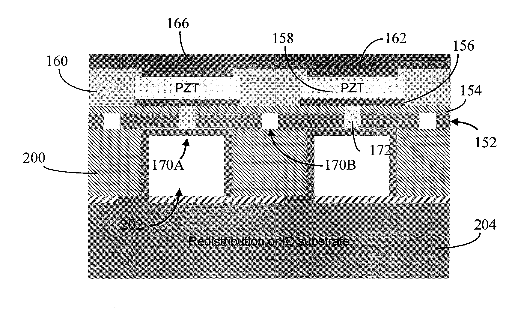
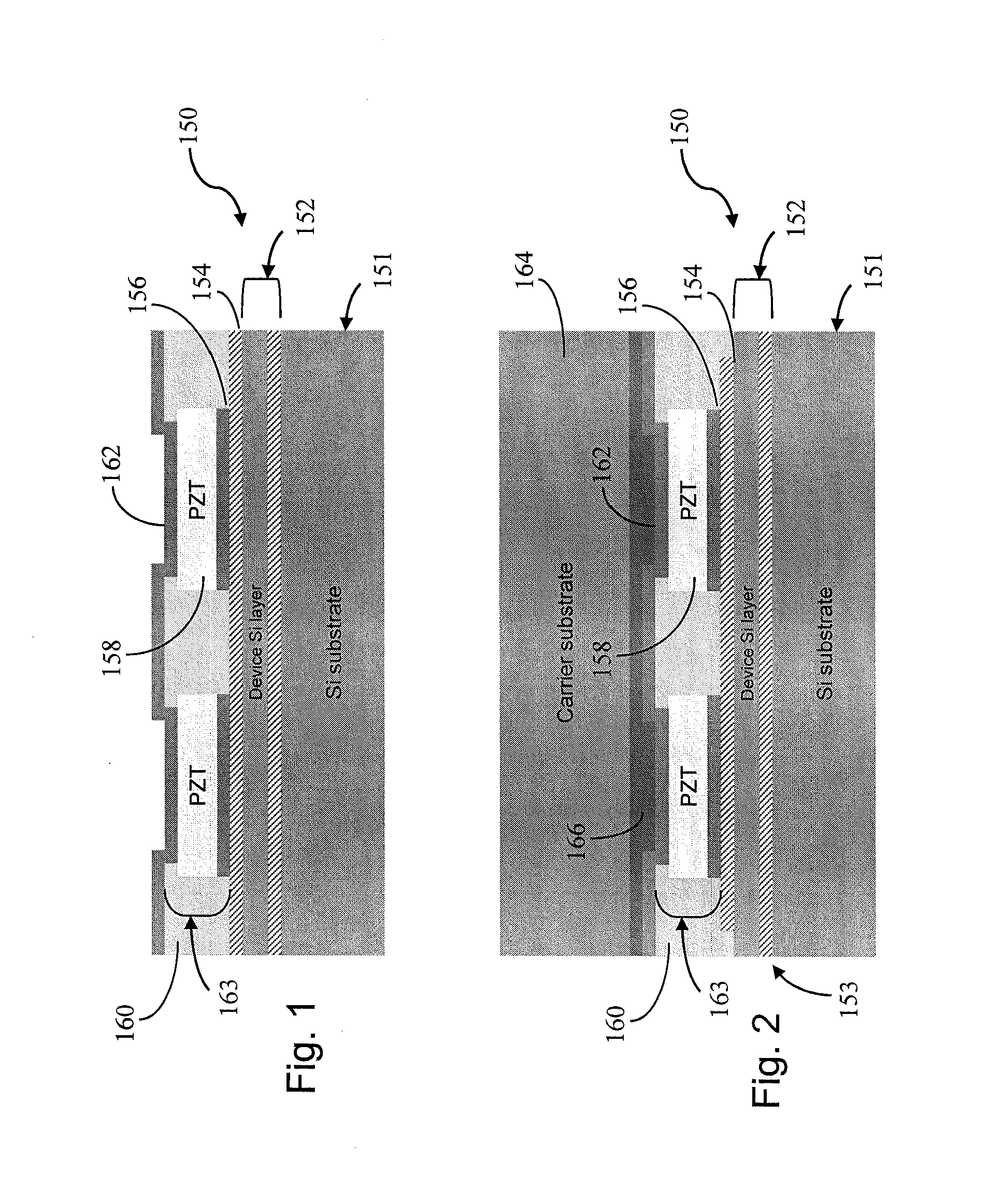
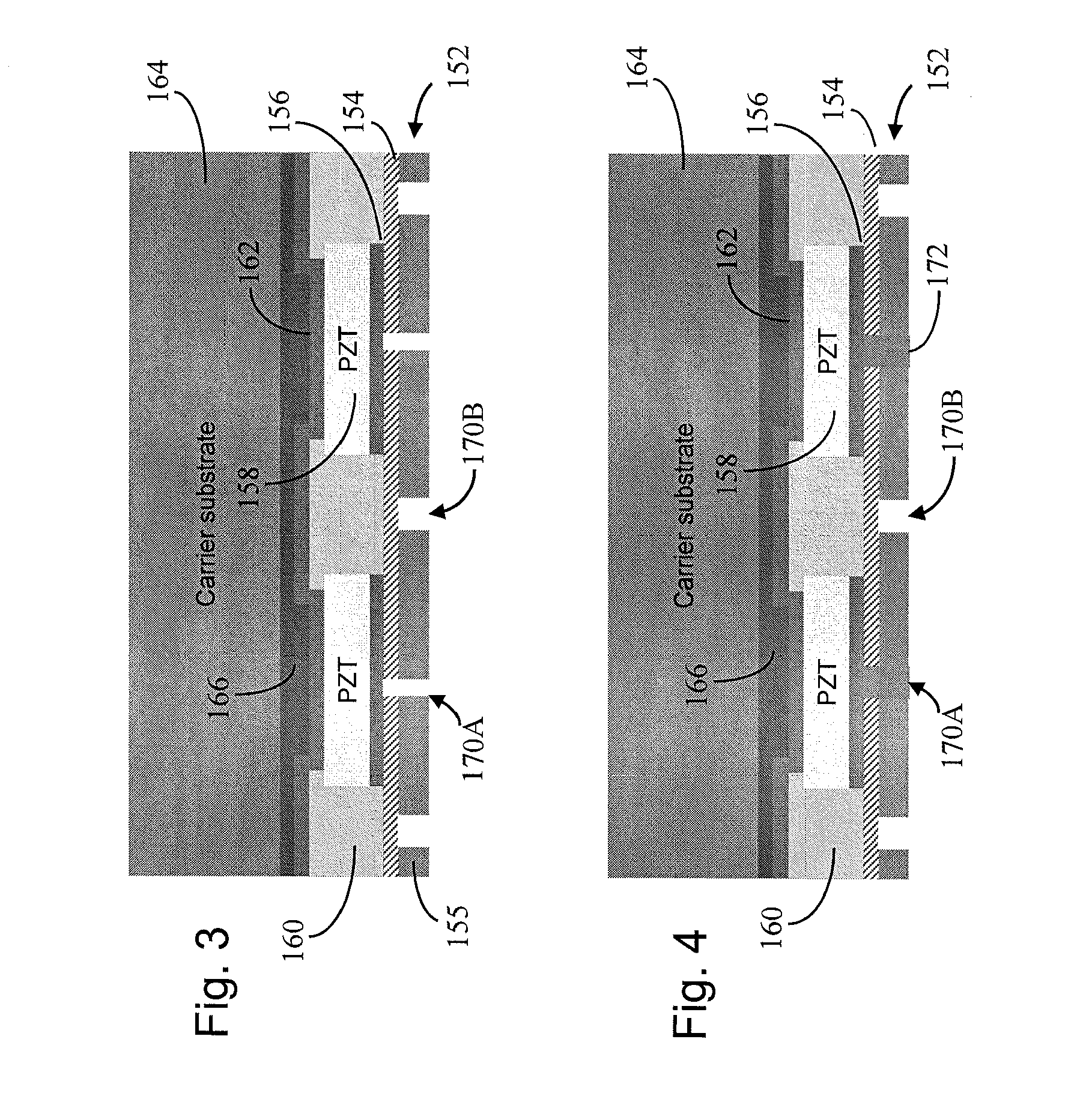
[0021]Aspects of the present disclosure are generally directed to methods for creating a metal or other electrically-conductive member extending from an air-backed cavity of a pMUT, through a substrate (i.e., SOI) layer disposed adjacent to the transducer device of the pMUT, and into electrically-conductive contact with the first / bottom electrode, such that the electrically-conductive member provides an improved electrically-conductive engagement between the first / bottom electrode and a conformal metal layer deposited in th...


PUM


Abstract

Methods are provided for creating a metal or other electrically-conductive member extending from an air-backed cavity of a piezoelectric ultrasonic transducer (pMUT) apparatus defining such an air-backed cavity, through a substrate layer disposed adjacent to the transducer device of the pMUT device, and into electrically-conductive engagement with a first electrode of the pMUT device, such that the electrically-conductive member provides an electrically-conductive engagement between the first electrode and a conformal electrically-conductive layer deposited in the air-backed cavity of the pMUT device. Associated apparatuses are also provided.

Description

FEDERALLY SPONSORED RESEARCH OR DEVELOPMENT[0001]This invention was made with United States Government support under Contract No. R33 EB00566 awarded by National Institutes of Health (NIH). The United States Government has certain rights in the invention.BACKGROUND OF THE DISCLOSURE[0002]1. Field of the Disclosure[0003]Aspects of the present disclosure relate to ultrasonic transducers, and, more particularly, to methods of forming a piezoelectric micromachined ultrasonic transducer defining an air-backed cavity, and associated apparatuses.[0004]2. Description of Related Art[0005]Some micromachined ultrasonic transducers (MUTs) may be configured, for example, as a piezoelectric micromachined ultrasonic transducer (pMUT) disclosed in U.S. Pat. No. 7,449,821 assigned to Research Triangle Institute, also the assignee of the present disclosure, which is also incorporated herein in its entirety by reference.[0006]The formation of pMUT device, such as the pMUT device defining an air-backed...

Claims


Application Information

Patent Timeline
Patent Type & Authority Applications(United States)
IPC IPC(8): H01L41/22H01L41/00H01L41/317
CPCB06B1/0622H01L41/09H01L41/313H01L41/29H01L41/0973H10N30/875H10N30/2047H10N30/06H10N30/073B06B1/06H10N30/87H10N30/01H10N30/20
Inventor DAUSCH, DAVID EDWARD
Owner RES TRIANGLE INST
Why Eureka
Try Eureka