Catadioptric system and image pickup apparatus

a catadioptric system and image pickup technology, applied in closed circuit television systems, television systems, instruments, etc., can solve the problems of insufficient observation area, insufficient field of view, and insufficient time, and achieve good both-side telecentric properties, reduce various aberrations over a wide wavelength range, and high resolution power

Inactive Publication Date: 2012-12-20
CANON KK
View PDF1 Cites 5 Cited by
  • Summary
  • Abstract
  • Description
  • Claims
  • Application Information

AI Technical Summary

Benefits of technology

[0009]The present invention provides a catadioptric system having a good both-side telecentric property, being capable of sufficiently reducing various aberrations over a wide wavelength range and achieving a high resolving power over a wide image-taking area.

Problems solved by technology

However, this method causes a problem of taking time because the image data is prepared by image taking of the pathology specimen.
However, although the microscope objective lens disclosed in Japanese Patent Laid-Open No. 60-034737 sufficiently reduces the aberrations over the entire visible wavelength range, it has an observation area which is not necessarily sufficiently large.
However, although the super-wideband ultraviolet microscope video system disclosed in Japanese translation of PCT international application No. 2001-517806 achieves a high resolving power by sufficiently reducing aberrations over the wide ultraviolet band, it has a field-of-view which is not necessarily sufficiently large.
However, although the catadioptric system disclosed in Japanese Patent Laid-Open No. 2002-082285 achieves a high resolving power by sufficiently reducing aberrations over the wide area, it has a long total length.
Such a long total optical system length increases the size of the exposure apparatus, which is inconvenient to install and operate the apparatus.

Method used


Image

  • Catadioptric system and image pickup apparatus
  • Catadioptric system and image pickup apparatus
  • Catadioptric system and image pickup apparatus

Examples


example 1

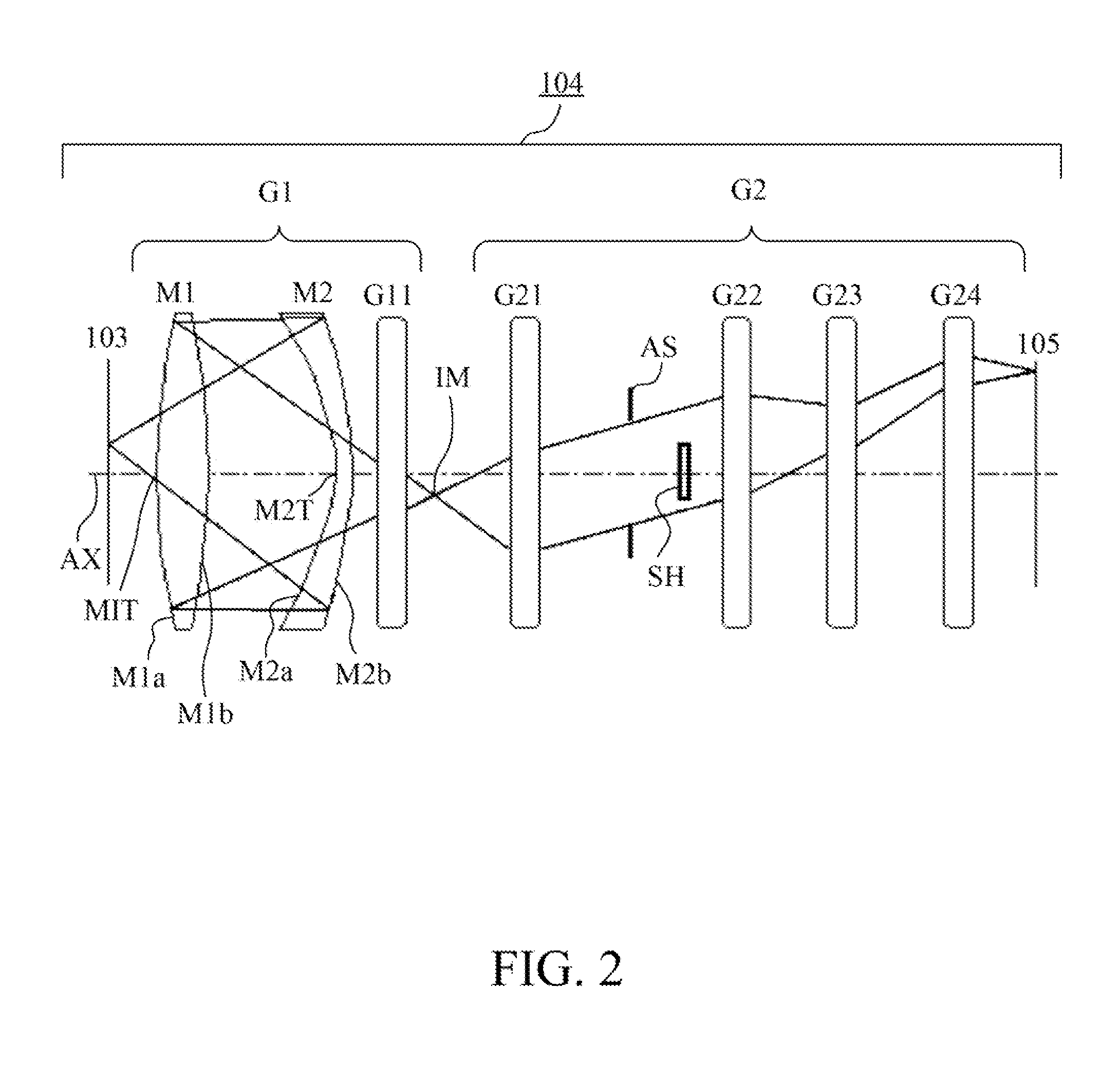
[0055]FIG. 3 is a cross-sectional view of main parts of the catadioptric system that is a first example (Example 1) of the present invention. In FIG. 3, reference numeral 104A denotes the catadioptric system, reference numeral 103 denotes the sample (object surface), and reference numeral 105 denotes the image pickup element (image surface). Reference character AS denotes the aperture stop, and reference character IM denotes the intermediate image. Moreover, reference character G1 denotes the first optical imaging system constituting the catadioptric part, and reference character G2 denotes the second optical imaging system constituting the dioptric part. The first optical imaging system G1 includes the first optical element (Mangin mirror) M1, the second optical element (Mangin mirror) M2 and the lens group G11. The second optical imaging system G2 includes the lens groups G21-G24 and the aperture stop AS.

[0056]In the catadioptric system 104A shown in FIG. 3, a light flux exiting f...

example 2

[0065]FIG. 5 is a cross-sectional view of main parts of the catadioptric system 104B that is a second example (Example 2) of the present invention. In FIG. 5, elements identical to those in FIG. 3 are denoted by the same reference numerals and characters as those in FIG. 3. The configuration of this example is nearly same as that of Example 1. The optical path of the light flux from the sample 103 to the passage through the second optical element M2 in this example is same as that in Example 1.

[0066]In this example, the light flux that has passed through the central transmissive portion M2T of the second optical element M2 passes through the lens group G11 (lenses L1-L3) and then forms the intermediate image IM of the sample 103. The light flux from the intermediate image IM sequentially passes through the lens group G21 (lenses L4-L7) having a positive refractive power, the aperture stop AS and the lens group G22 (lenses L8-L10) having a positive refractive power. The light flux fu...

example 3

[0072]FIG. 7 is a cross-sectional view of main parts of the catadioptric system 104C that is a third example (Example 3) of the present invention. In FIG. 7, elements identical to those in FIG. 3 are denoted by the same reference numerals and characters as those in FIG. 3. The configuration of this example is nearly same as that of Example 1, but is different from that of Example 1 in that the second optical imaging system G2 is constituted by lens groups G21 to G25. The lens group G21 constitutes a front lens group, and the lens groups G22-G25 constitute a rear lens group.

[0073]The optical path of the light flux from the sample 103 to the passage through the second optical element M2 in this example is same as that in Example 1. In this example, the light flux that has passed through the central transmissive portion M2T of the second optical element M2 passes through the lenses L1 and L2 and then forms inside the lens L3 the intermediate image IM of the sample 103. The light flux f...


PUM


Abstract

The catadioptric system includes a first optical imaging system (catadioptric part) causing a light flux from an object to form an intermediate image and a second optical imaging system (dioptric part) causing the light flux from the intermediate image to form an image. In the first optical imaging system, the light flux sequentially passes a first transmissive portion, a second reflective portion, a first reflective portion and a second transmissive portion. In the second optical imaging system, consecutive four lens surfaces among plural lens surfaces placed between an aperture stop and an image surface have a negative combined refractive power, and a condition of −0.52<φ4n<sub2>—</sub2>max·Ymax<−0.14 is satisfied, φ4n<sub2>—</sub2>max represents a maximum value of the negative combined refractive power, and Ymax represents a maximum object height in a field-of-view of the catadioptric system at the object.

Description

TECHNICAL FIELD[0001]The present invention relates to a catadioptric system suitable for enlarging and observing a sample (object), and to an image pickup apparatus with the same.BACKGROUND ART[0002]In recent pathological examinations, an examiner observes pathological specimens (samples) not only directly with his / her eyes through an optical microscope, but also through image data taken by a virtual microscope and displayed on a display device. Such a virtual microscope enables plural examiners to simultaneously observe the image data of the pathological specimen displayed on the display device. Moreover, the virtual microscope provides many advantages including sharing of the image data with a distant pathologist to ask him / her for diagnosis. However, this method causes a problem of taking time because the image data is prepared by image taking of the pathology specimen.[0003]One reason for taking time is that the image data is taken by using a conventional virtual microscope with...

Claims


Application Information

Patent Timeline
Patent Type & Authority Applications(United States)
IPC IPC(8): G02B17/08H04N7/18
CPCG02B17/0808G02B13/24G02B17/08G02B21/00G02B21/02
Inventor KATASHIBA, YUJIKAJIYAMA, KAZUHIKOSUZUKI, MASAYUKI
Owner CANON KK
Why Eureka
Try Eureka