
Smart-phone adapter for ophthalmoscope

a technology for ophthalmoscopes and smart phones, applied in the field of ophthalmoscopes, can solve the problems of cumbersome, bulky, unwieldy, and misalignment between the optical axis of the camera and the optical axis of the instrumen

Inactive Publication Date: 2012-12-20
INTUITIVE MEDICAL TECH
View PDF3 Cites 250 Cited by
  • Summary
  • Abstract
  • Description
  • Claims
  • Application Information

AI Technical Summary

Benefits of technology

[0012]In another aspect of the invention, the adapter can be used with other types of medical viewing instruments as well as with other types of scopes in other industries. The adapter can be modular so that the bracket and frame can hold a particular type of camera, and the fitting for the eyepiece section of the bracket and the brace for the body section of the bracket can be selected for the particular scope or other viewing instrument to which the camera is to be coupled. In yet another aspect of the invention, the adapter system can be used with a smart-phone or other mobile communications device operating as the image capture device and the processor of such a

Problems solved by technology

However, since many digital cameras and imaging smart-phones only have a single, integral lens system and no longer have any mounting device for different lenses, some adapters now secure the image capture device by its outer housing where a user would hold the device.
Since the lenses in many digital cameras, especially smart-phone devices, are offset from the center of gravity, the eyepiece connection is more likely to result in a misalignment between the optical axis of the camera and the optical axis of the instrument.
There have been some efforts to accommodate this misalignment, but they have been cumbersome, bulky and unwieldy.
However, none of the present systems describe or suggest an adapter which has a single bracket which is attached to both the view port of the viewing instrument through a fitting as well as the handle of the viewing instrument through a brace where this same bracket also has a frame that holds the camera in place so that its lens is aligned with the optical axis the viewing instrument.

Method used


Image

  • Smart-phone adapter for ophthalmoscope
  • Smart-phone adapter for ophthalmoscope
  • Smart-phone adapter for ophthalmoscope

Examples


Embodiment Construction

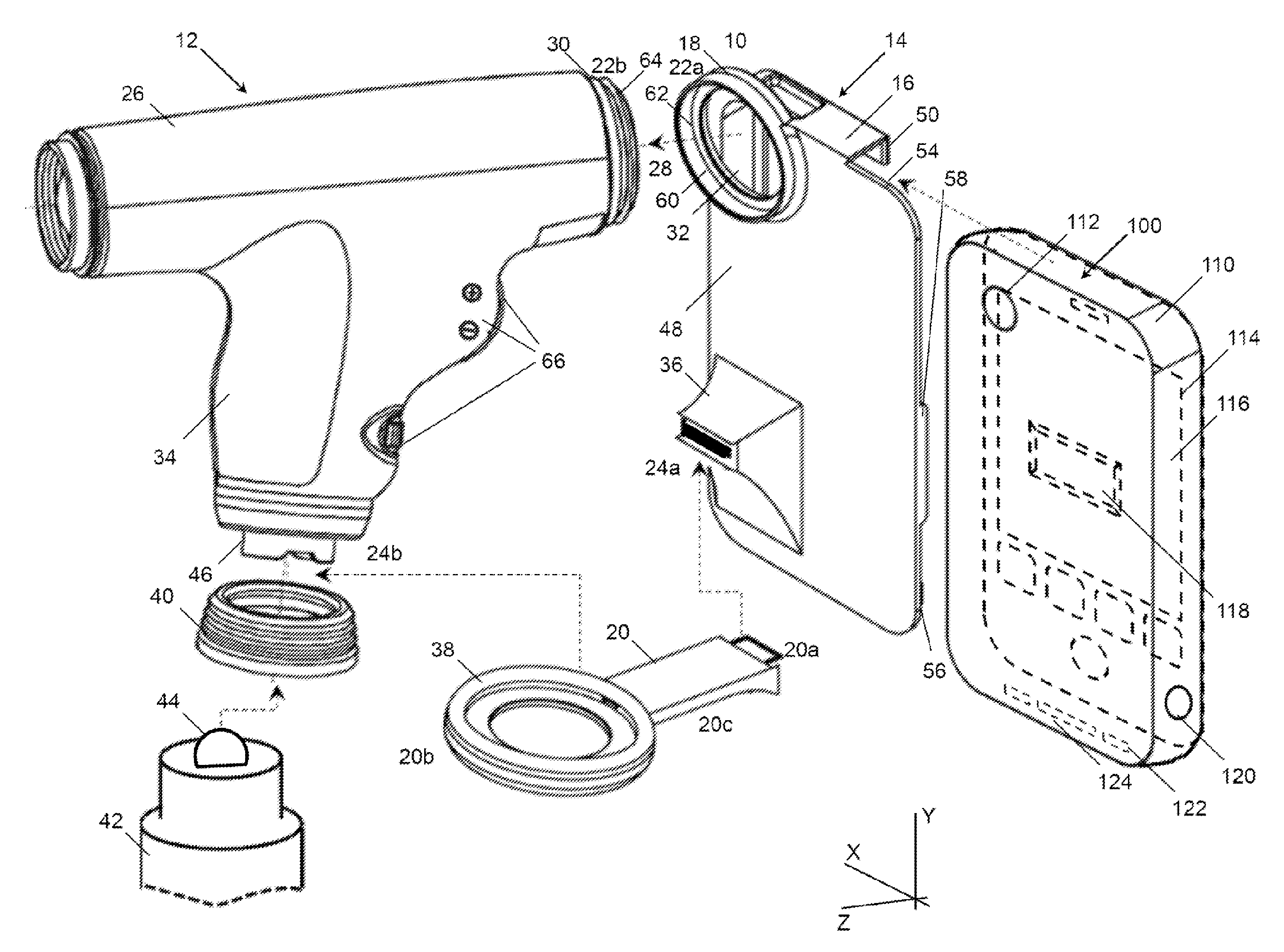
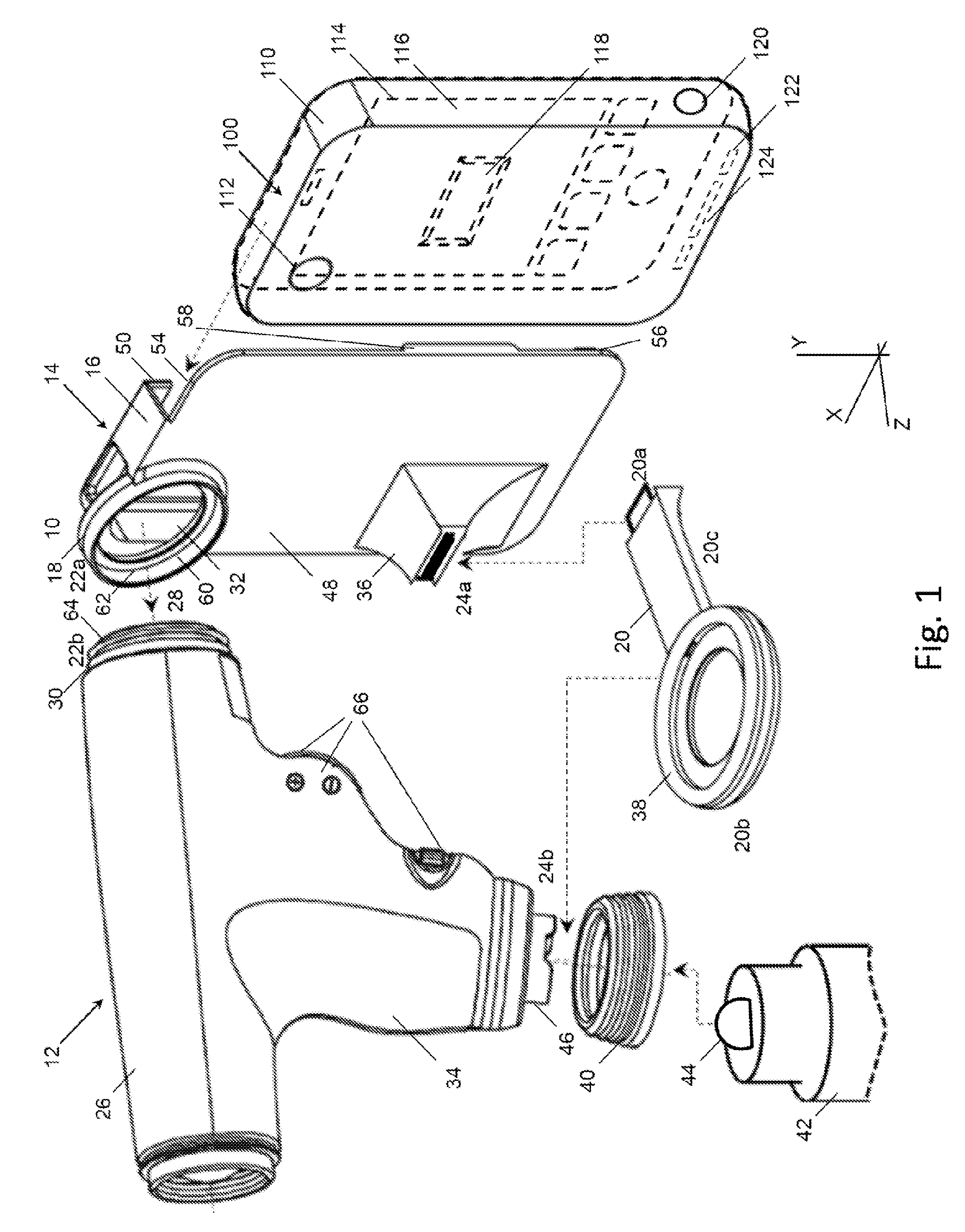
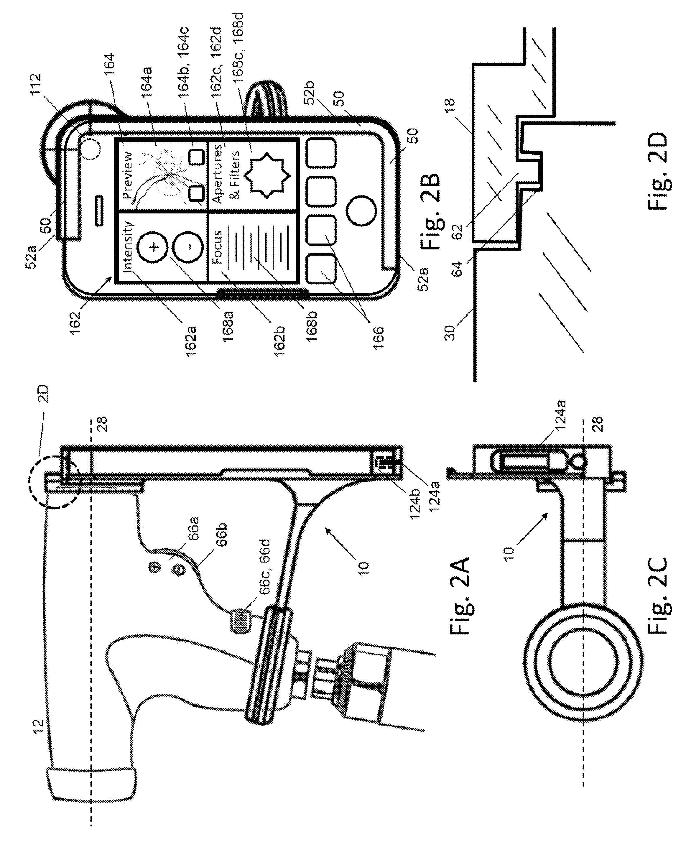
[0020]Described herein is an adapter 10 which holds a viewing instrument 12 in an aligned relationship with an imaging device that captures images of the subject being viewed. In the particular embodiment described herein, the viewing instrument is an ophthalmoscope 26 and the ophthalmological imaging apparatus allows a medical practitioner to easily view and record images of the retina and the anterior segments of the eye, including the optic nerve. Further, the ophthalmological imaging apparatus provides the medical practitioner with a complete view of the entire optic nerve, not just a partial view. Additionally, the ophthalmological imaging apparatus provides the medical practitioner with a full image of a patient's eye. Accordingly, it will be appreciated that the users of the present device can be a range of medical practitioners, such as optometrists, doctors, and nurses. It will also be appreciated that the preferred embodiment described herein is exemplary in nature, and as...


PUM


Abstract

An adapter system connects a smart-phone or other camera to an ophthalmoscope or other viewing instrument at multiple locations with a single bracket. A fitting attached to the bracket connects the adapter to the viewing instrument in the region near its view port, close to the optical axis. A brace attached to the bracket connects the adapter to the viewing instrument in the region of the instrument's handle or other support structure, located away from the optical axis. The brace has a frame that holds the camera in place and aligns the camera lens with the optical axis of the instrument. The processor of the smart-phone or other mobile communications device can provide specific information related to the particular viewing instrument and can also be used in the operation and control of smart-scope instruments through a communications link.

Description

CROSS-REFERENCE TO RELATED APPLICATIONS[0001]This application claims priority from U.S. Provisional Patent Application Nos. 61 / 498,551 and 61 / 541,105 as filed on Jun. 18, 2011 and Sep. 30, 2011 and which are incorporated by reference herein.STATEMENT REGARDING FEDERALLY SPONSORED RESEARCH[0002]Not Applicable.APPENDIX[0003]Not Applicable.BACKGROUND OF THE INVENTION[0004]1. Field of the Invention[0005]The present invention relates to ophthalmoscopes, and more particularly to adapters for holding an image capture device in an optical alignment with the eyepiece of the ophthalmoscopes and other viewing instruments.[0006]2. Related Art[0007]There are a number of hand-held ophthalmoscopes which include the ability to capture images of a patient's eye. Some of these hand-held instruments have included interchangeable instrument heads which can be used for a variety of medical examinations and could capture images of the patient's anatomy, either with still pictures or video. Most systems t...

Claims


Application Information

Patent Timeline
IPC IPC(8): A61B3/15
CPCA61B3/14A61B3/1208A61B3/10
Inventor COLEMAN, III, WYCHE T.
Owner INTUITIVE MEDICAL TECH
Learn More