Motion vector estimation method, multiview video encoding method, multiview video decoding method, motion vector estimation apparatus, multiview video encoding apparatus, multiview video decoding apparatus, motion vector estimation program, multiview video encoding program, and multiview video decoding program

a multi-view video encoding and estimation method technology, applied in the direction of color television with bandwidth reduction, signal generator with optical-mechanical scanning, signal generator, etc., can solve the problem of encoding distortion called drift, and achieve the effect of accurately estimating a motion vector and efficient multi-view video encoding

Inactive Publication Date: 2012-12-20
NIPPON TELEGRAPH & TELEPHONE CORP
View PDF7 Cites 19 Cited by
  • Summary
  • Abstract
  • Description
  • Claims
  • Application Information

AI Technical Summary

Benefits of technology

[0038]The present invention can estimate a motion vector accurately even in a situation in which a processing picture cannot be obtained, and can realize efficient multiview vid...

Problems solved by technology

However, in general, when predictive encoding is performed, if a depth map used at an encodin...

Method used


Image

  • Motion vector estimation method, multiview video encoding method, multiview video decoding method, motion vector estimation apparatus, multiview video encoding apparatus, multiview video decoding apparatus, motion vector estimation program, multiview video encoding program, and multiview video decoding program
  • Motion vector estimation method, multiview video encoding method, multiview video decoding method, motion vector estimation apparatus, multiview video encoding apparatus, multiview video decoding apparatus, motion vector estimation program, multiview video encoding program, and multiview video decoding program
  • Motion vector estimation method, multiview video encoding method, multiview video decoding method, motion vector estimation apparatus, multiview video encoding apparatus, multiview video decoding apparatus, motion vector estimation program, multiview video encoding program, and multiview video decoding program

Examples


first embodiment

A. First Embodiment

[0062]First, a first embodiment of the present invention will be described.

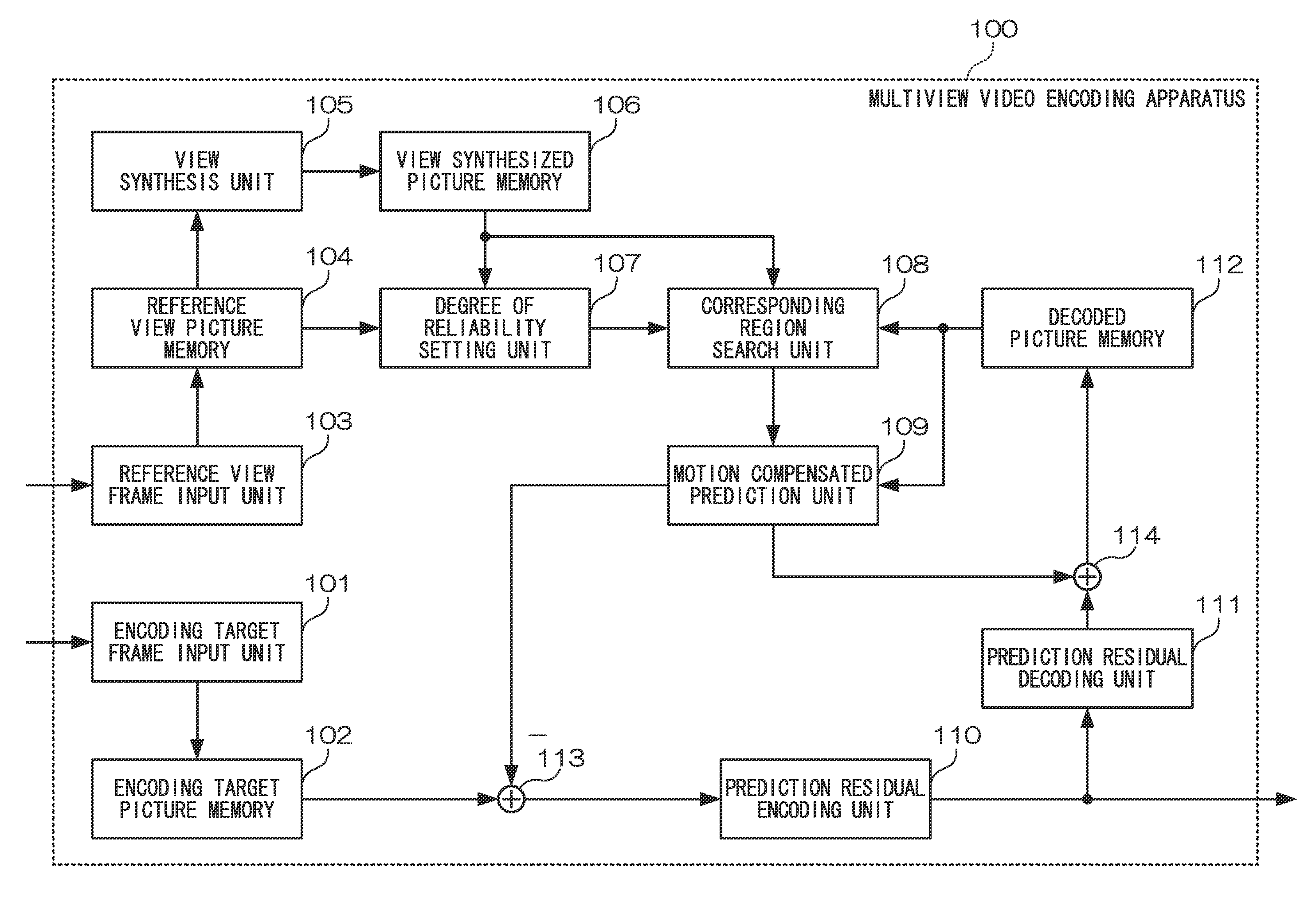
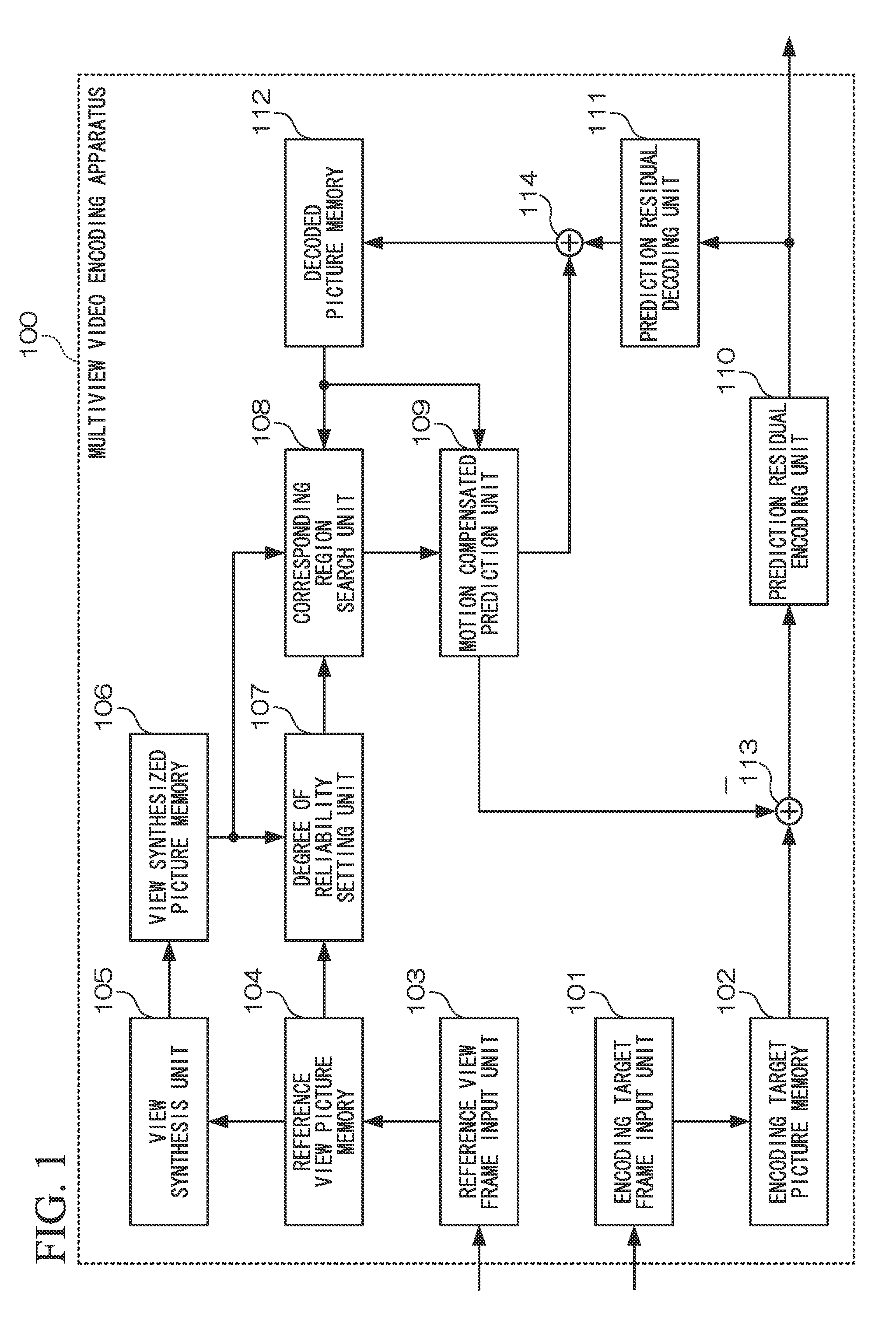
[0063]FIG. 1 is a block diagram illustrating a configuration of a multiview video encoding apparatus in the first embodiment. As illustrated in FIG. 1, the multiview video encoding apparatus 100 is provided with an encoding target frame input unit 101, an encoding target picture memory 102, a reference view frame input unit 103, a reference view picture memory 104, a view synthesis unit 105, a view synthesized picture memory 106, a degree of reliability setting unit 107, a corresponding region search unit 108, a motion compensated prediction unit 109, a prediction residual encoding unit 110, a prediction residual decoding unit 111, a decoded picture memory 112, a prediction residual calculation unit 113, and a decoded picture calculation unit 114.

[0064]The encoding target frame input unit 101 inputs a video frame (encoding target frame) serving as an encoding target. The encoding target pic...

second embodiment

B. Second Embodiment

[0108]Next, a second embodiment of the present invention will be described.

[0109]FIG. 3 is a block diagram illustrating a configuration of a multiview video encoding apparatus in the second embodiment. As illustrated in FIG. 3, the multiview video encoding apparatus 200 is provided with an encoding target frame input unit 201, an encoding target picture memory 202, a reference view frame input unit 203, a view synthesis unit 204, a view synthesized picture memory 205, a motion estimation unit 206, a motion compensated prediction unit 207, a picture encoding unit 208, a picture decoding unit 209, a decoded picture memory 210, a corresponding region search unit 211, a prediction vector generation unit 212, a vector information encoding unit 213, and a motion vector memory 214.

[0110]The encoding target frame input unit 201 inputs a video frame serving as an encoding target. The encoding target picture memory 202 stores the input encoding target frame. The reference ...

third embodiment

C. Third Embodiment

[0135]Next, a third embodiment of the present invention will be described.

[0136]FIG. 5 is a block diagram illustrating a configuration of a multiview video decoding apparatus in the third embodiment. As illustrated in FIG. 5, the multiview video decoding apparatus 300 is provided with an encoded data input unit 301, an encoded data memory 302, a reference view frame input unit 303, a reference view picture memory 304, a view synthesis unit 305, a view synthesized picture memory 306, a degree of reliability setting unit 307, a corresponding region search unit 308, a motion compensated prediction unit 309, a prediction residual decoding unit 310, a decoded picture memory 311, and a decoded picture calculation unit 312.

[0137]The encoded data input unit 301 inputs encoded data of a video frame serving as a decoding target. The encoded data memory 302 stores the input encoded data. The reference view frame input unit 303 inputs a video frame (reference view frame) for ...


PUM


Abstract

Efficient multiview video encoding is realized even in a situation in which a processing picture cannot be obtained, by accurately estimating a motion vector and simultaneously using an inter-camera correlation and a temporal correlation in prediction of a video signal. A view synthesized picture at a time when a processing picture has been taken is generated from a reference camera video that has been taken by a camera different from a processing camera that has taken the processing picture included in a multiview video based on the same setting as that of the processing camera. A motion vector is estimated by searching for a corresponding region in a reference picture taken by the processing camera using a picture signal on the view synthesized picture corresponding to a processing region on the processing picture without using the processing picture.

Description

TECHNICAL FIELD[0001]The present invention relates to a motion vector estimation method, a multiview video encoding method, a multiview video decoding method, a motion vector estimation apparatus, a multiview video encoding apparatus, a multiview video decoding apparatus, a motion vector estimation program, a multiview video encoding program, and a multiview video decoding program.[0002]Priority is claimed on Japanese Patent Application No. 2010-037434, filed Feb. 23, 2010, the content of which is incorporated herein by reference.BACKGROUND ART[0003]Multiview moving pictures (multiview video) are a group of moving pictures obtained by photographing the same object and background using a plurality of cameras. In typical moving picture encoding, efficient encoding is realized using motion compensated prediction that utilizes a high correlation between frames at different times in moving pictures. The motion compensated prediction is a technique adopted in recent international standard...

Claims


Application Information

Patent Timeline
IPC IPC(8): H04N7/32
CPCH04N19/597H04N19/105H04N19/52H04N19/176H04N19/51H04N19/109H04N19/137H04N19/44H04N19/80H04N19/567H04N19/573H04N19/521H04N13/00
Inventor SHIMIZU, SHINYAKIMATA, HIDEAKIMATSUURA, NORIHIKO
Owner NIPPON TELEGRAPH & TELEPHONE CORP
Why Eureka
Try Eureka