Method for automatic mismatch correction of image volumes

a technology of image volume and automatic mismatch correction, applied in image analysis, image enhancement, instruments, etc., can solve the problems of laborious and expensive process, difficult to meet assumption, and difficult to obtain the history of the patient,

Active Publication Date: 2012-12-20
GENERAL ELECTRIC CO
View PDF4 Cites 13 Cited by
  • Summary
  • Abstract
  • Description
  • Claims
  • Application Information

AI Technical Summary

Benefits of technology

[0005]In accordance with aspects of the present technique, a method for automatic mismatch correction of image volumes is presented. The method includes identifying a feature of interest in a reference image volume and a target image volume. Furthermore, the method includes computing a cost matrix based on one or more pairs of image slices in the reference image volume and the target image volume. The method also includes identifying one or more longest common matching regions in the reference image volume and the target image volume based on the computed cost matrix. In addition, the method includes aligning the reference image volume and the target image volume based on the identified one or more longest common matching regions. A non-transitory computer readable medium including one or more tangible med

Problems solved by technology

The use of multi-modality radiological images, such as, but not limited to, CT images, magnetic resonance (MR) images, positron emission tomography (PET) images, and/or ultrasound (US) images, as well as histopathological images makes this task extremely challenging.
Unfortunately, this assumption may not be satisfied for oncology studies where significant amounts of field-of-view (FOV) or coverage mismatch may occur between multi-time point image volumes.
This mismatch may be a result of modality (e.g., long acquisition time for magnetic resonance imaging (MRI)) or physiological (e.g., dose related issues for CT) limitations.
Unfortunately, estimation of a minimum-cost straight line

Method used


Image

  • Method for automatic mismatch correction of image volumes
  • Method for automatic mismatch correction of image volumes
  • Method for automatic mismatch correction of image volumes

Examples


Embodiment Construction

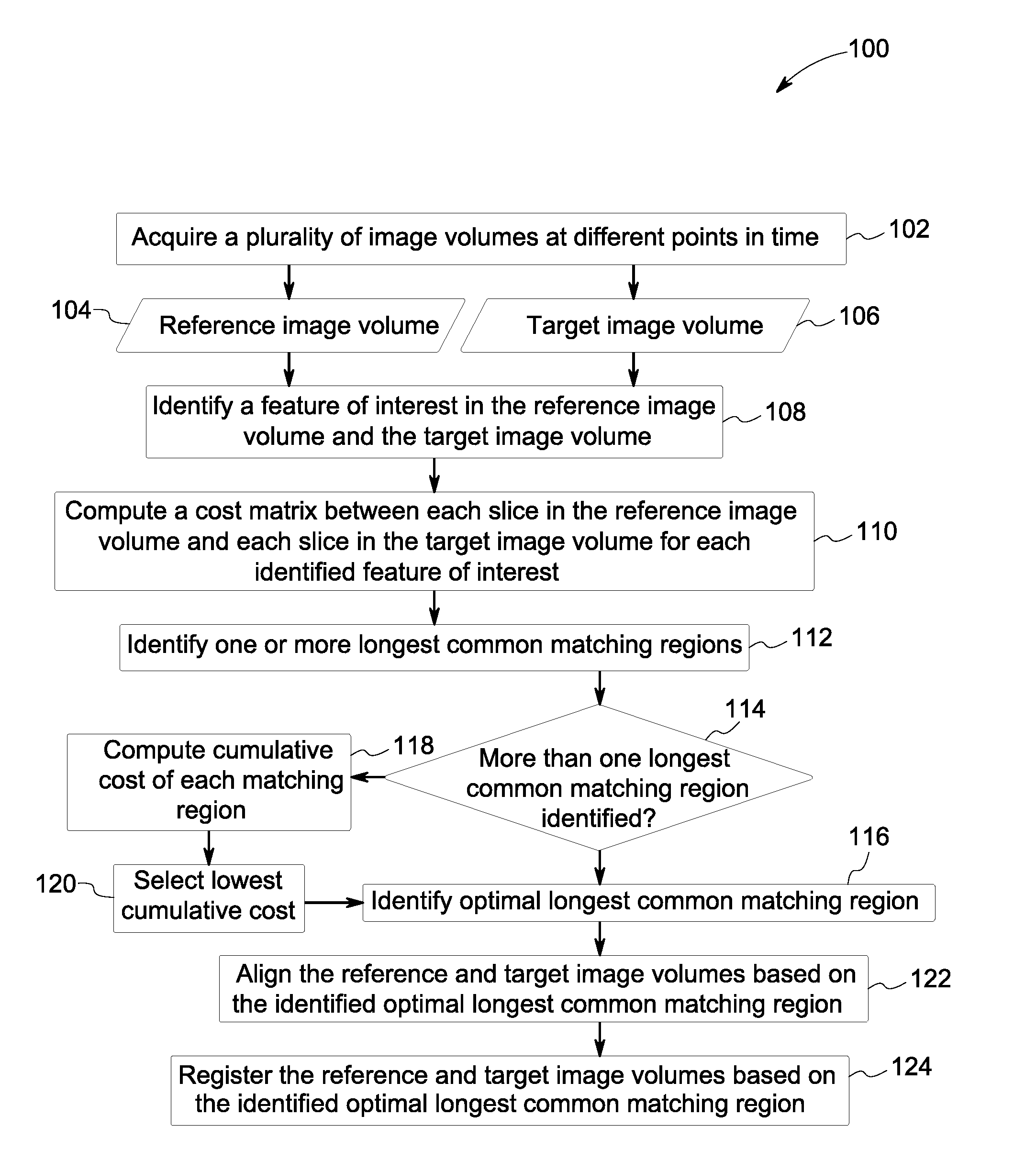
[0019]As will be described in detail hereinafter, a method and system for the automated mismatch correction of multi-point (longitudinal) image volumes are presented. Use of these approaches enhances the quality of diagnosis, therapy and / or follow-up studies.

[0020]Referring now to FIG. 1, a flow chart 100 depicting an exemplary method for the automated mismatch correction of longitudinal image volumes is presented. As used herein, the term “longitudinal image volumes” is used to refer to image volumes corresponding to an object of interest acquired at different points in time. The method starts at step 102 where one or more longitudinal image volumes are acquired. Particularly, image volumes representative of a region of interest in an object of interest may be acquired. Also, the object of interest may be a patient, in certain embodiments. By way of example, image volumes representative of a thoracic region in the patient may be acquired. These longitudinal image volumes may be use...


PUM


Abstract

A method for automatic mismatch correction is presented. The method includes identifying a feature of interest in a reference image volume and a target image volume. Furthermore, the method includes computing a cost matrix based on one or more pairs of image slices in the reference image volume and the target image volume. The method also includes identifying one or more longest common matching regions in the reference image volume and the target image volume based on the computed cost matrix. In addition, the method includes aligning the reference image volume and the target image volume based on the identified one or more longest common matching regions. A non-transitory computer readable medium including one or more tangible media, where the one or more tangible media include code adapted to perform the method for automatic mismatch correction is also presented. Systems and non-transitory computer readable medium configured to perform the method for automatic mismatch correction of image volumes are also presented.

Description

CROSS REFERENCE TO RELATED APPLICATIONS[0001]This non-provisional application claims the benefit of priority under 35 U.S.C. §119(e) to India Provisional Patent Application Serial No. 2056 / CHE / 2011, filed Jun. 17, 2011, which is herein incorporated in its entirety by reference.BACKGROUND[0002]Analysis of computed tomography (CT) image volumes by clinicians, such as radiologists, calls for co-registration of the image volumes. Particularly, in oncology studies, it is desirable to co-register longitudinal image volumes having disparate coverage areas. Accordingly, three-dimensional (3D) image volume registration is an essential feature for diagnosis, therapy, and treatment follow-up when dealing with longitudinal (i.e., multi-time point) oncology studies. The use of multi-modality radiological images, such as, but not limited to, CT images, magnetic resonance (MR) images, positron emission tomography (PET) images, and / or ultrasound (US) images, as well as histopathological images make...

Claims


Application Information

Patent Timeline
IPC IPC(8): G06K9/46
CPCG06K2209/05G06T2200/04G06T2207/10072G06T2207/30004G06T7/33G06V2201/03
Inventor JHUNJHUNWALA, PRIYAVRATTHIRUVENKADAM, SHESHADRIMULLICK, RAKESHNATH, SUMIT KUMAR
Owner GENERAL ELECTRIC CO
Why Eureka
Try Eureka