Road paver with layer thickness measuring device

Active Publication Date: 2012-12-20
JOSEPH VOEGELE AG
View PDF10 Cites 22 Cited by
  • Summary
  • Abstract
  • Description
  • Claims
  • Application Information

AI Technical Summary

Benefits of technology

[0024]In a further advantageous embodiment of the invention, the measuring device comprises at least two additional sensors in order to measure a distance to the plane where no new road pavement has yet been laid. These sensors are arranged relative to the first sensor in the direction of travel in such a way that they are positioned in front of the screed. The sensors are preferably arranged on the mounting element equidistantly or are supported on the holders mounted to the mounting element and equidistant to one another, whereby the holders can be adjusted in such a way that the sensors are spaced at a certain distance to the plane. The adjustable holders make it possible to hold the sensors at different heights above the plane according to their specific characteristics, particularly with regard to their measuring sensitivity.
[0025]It is also advantageous if the sensors, whether for measuring the distance to the newly laid road pavement layer or for measuring the distance to the plane, are formed to carry out the respective distance measurement continuously. In this way, it is possible to avoid delays when determining the layer thickness, which leads to a faster measurement result. As an alternative to this, however, it is also possible to operate all sensors in such a way that these can then be activated in cycles w

Problems solved by technology

If the calculated layer thickness of, for example, a bituminous layer, is too small, then there is a danger that the road pavement will break apart too early and leave behind potholes in this place.
This results in expensive subsequent improvements to the road pavement.
On the other hand, it is important to check the layer thickness with respect to whether or not it complies with an admissible maximum dimension, in order to avoid unnecessarily laying too much material, which would make the production more expensive.
It is disadvantageous that the systems have to be relocated over and over, which necessitates additional operating personnel.
It is also disadvantageous that the limit areas of the superimposed layers, for example, the area between the plane and the newly laid road pavement or also the surface of the constructed road pavement, can be registered only with difficulty and imprecision.
This, however, leads to additional costs for the provision of the reflective bodies and demands a great deal of time for the distribution of the same.
Finally, the placement of the reflective bodies can also result in irreparable damage to the road pavement.
As a result of the insertion, however, holes remain in the layer, whereby water can possibly collect in these holes, which results in further damage.

Method used


Image

  • Road paver with layer thickness measuring device
  • Road paver with layer thickness measuring device
  • Road paver with layer thickness measuring device

Examples


Example

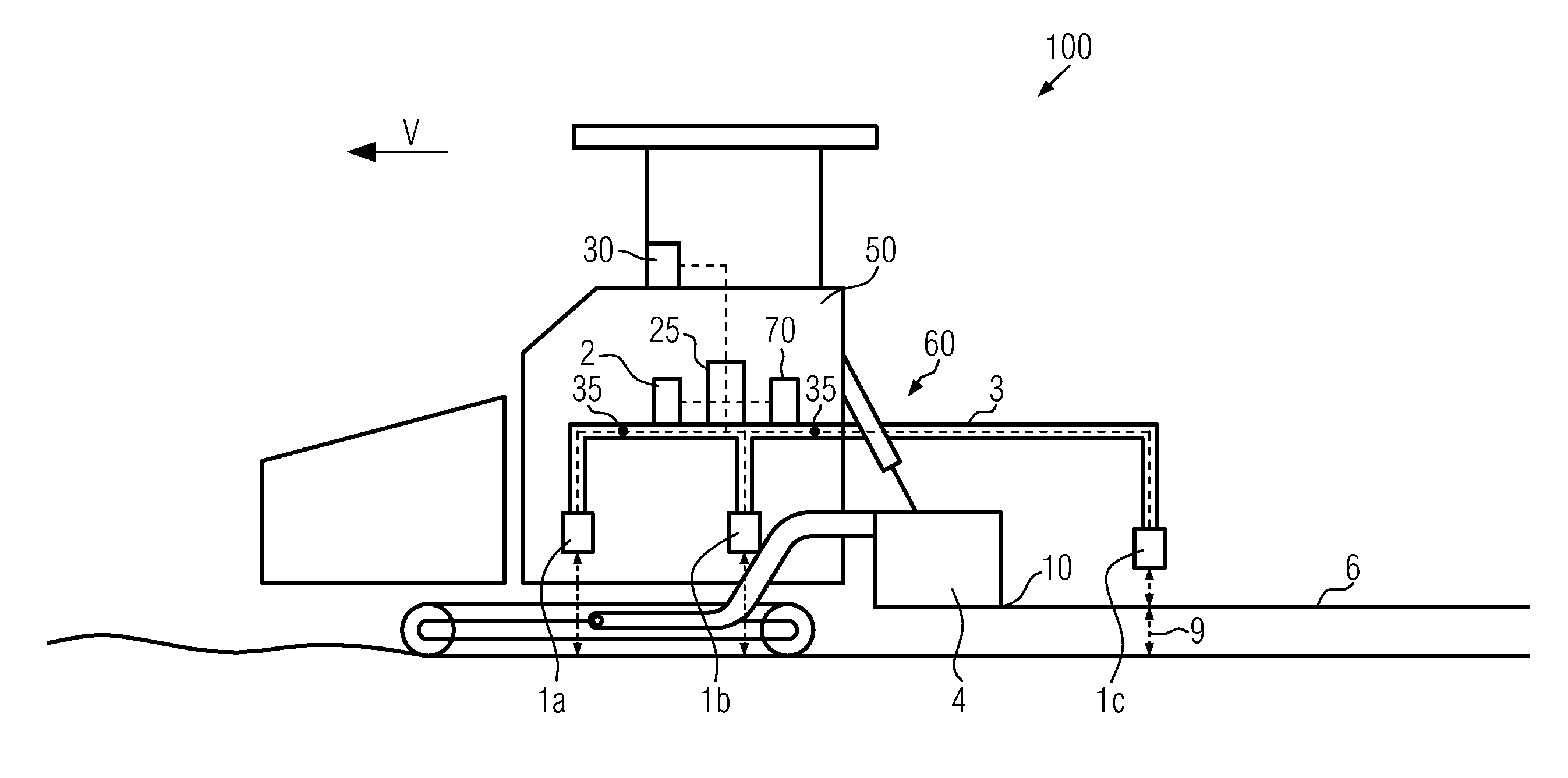
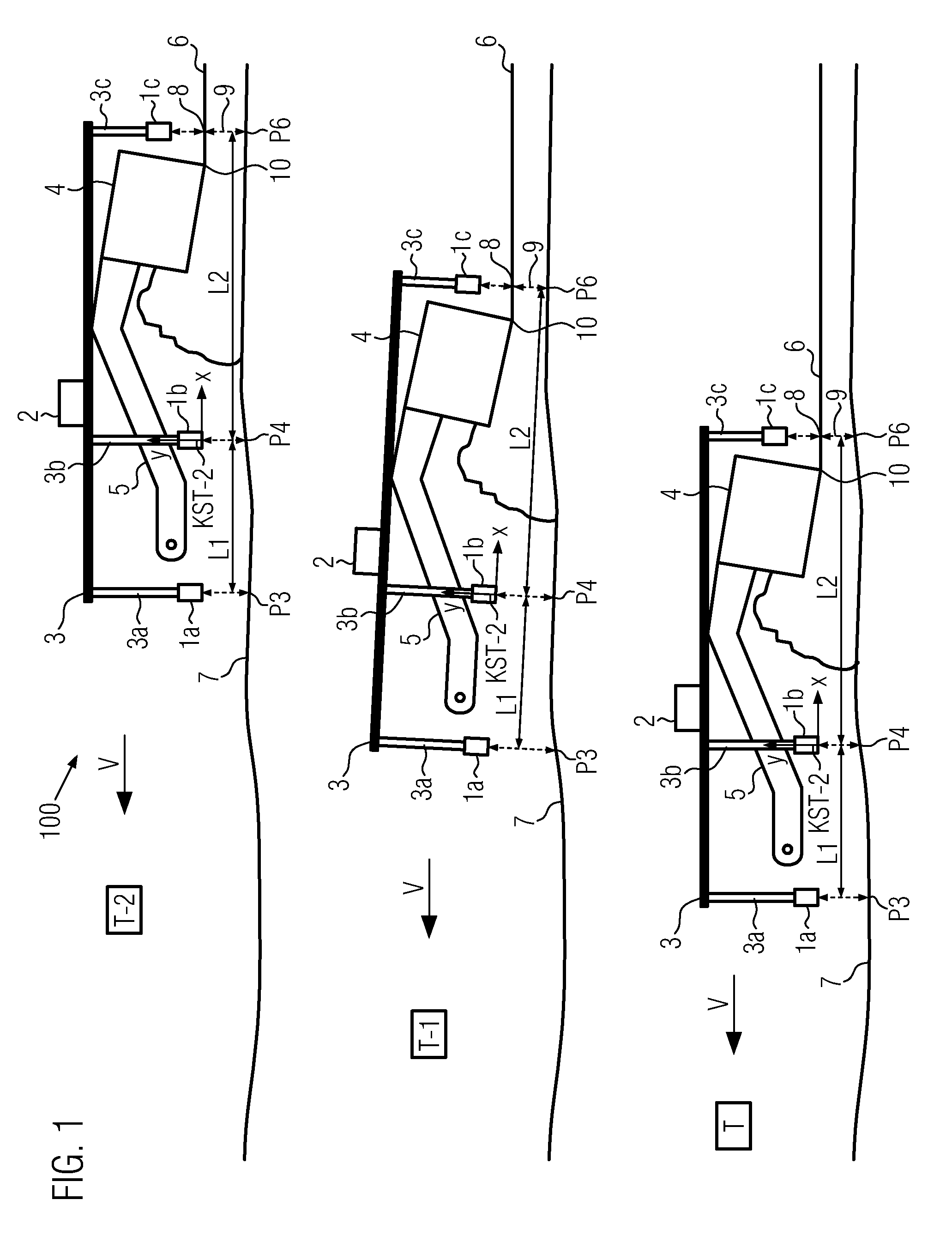
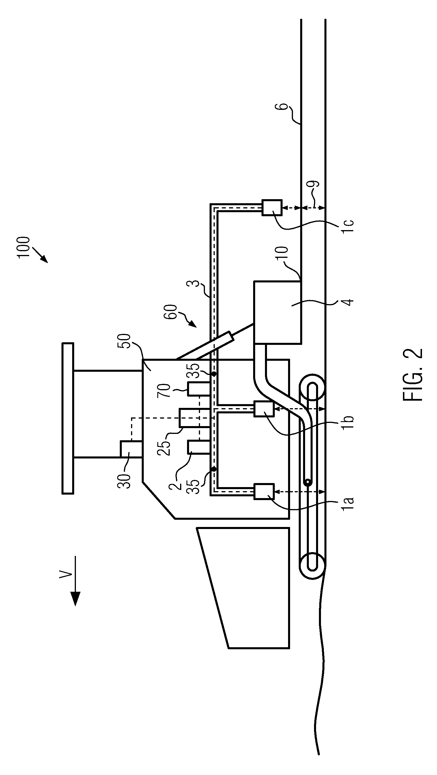
[0042]FIG. 1 shows a measuring device 60 that is depicted at different points in time T, T-1 and T-2 along a direction of travel V. The measuring device is arranged rigidly on a road paver 100, particularly on its towing machine 50. The road paver 100 is only suggested in FIG. 1, but is shown in FIG. 2. The road paver 100 moves along the direction of travel V on a subgrade 7 onto which the material for the new road pavement layer is to be laid. As shown by FIG. 1, the subgrade 7 has a wavy surface which causes the towing machine 50, including the measuring device 60 rigidly mounted upon it, to tilt back and forth along the paving section. The newly driven road pavement 6 forms a new driving surface whose layer thickness 9 can be determined by the measuring device 60 during the paving run of the road paver 100.

[0043]The measuring device 60 comprises a mounting element 3, which is aligned essentially horizontally with respect to the subgrade 7. The mounting element 3 can be present in...


PUM


Abstract

Road paver with a towing machine and a movable screed and with a measuring device that is provided for determining a layer thickness of a road pavement that has been newly laid by the screed. The measuring device is formed to determine the layer thickness at an intended location, seen relative to a direction of travel, behind a rear edge of the screed, whereby the measuring device is provided on the road paver such that the layer thickness can be determined independently of a geometric shape and/or a movement of the screed.

Description

FIELD OF THE INVENTION[0001]The present invention relates to a road paver with a towing machine and a movable screed and with a measuring device for determining the thickness of a layer of road pavement that has been newly laid by the screed. The measuring device is formed to determine the layer thickness at an intended location, seen relative to a direction of travel (V), behind a rear edge of the screed. Road pavers of this kind are used in practice in order to determine a layer thickness of the newly laid road pavement during a paving run.BACKGROUND OF THE INVENTION[0002]The laid road pavement is preferably a bituminous material, but can be sandy or stony layers or concrete. The determination of the layer thickness is therefore important in order to check the quality of the newly laid road pavement. If the calculated layer thickness of, for example, a bituminous layer, is too small, then there is a danger that the road pavement will break apart too early and leave behind potholes...

Claims


Application Information

Patent Timeline
IPC IPC(8): E01C19/22
CPCG01B21/08G01B21/18E01C19/48
Inventor HANFLAND, DENNISWEISER, RALF
Owner JOSEPH VOEGELE AG
Why Eureka
Try Eureka