Press-forming method and press-forming apparatus

Active Publication Date: 2012-12-27
HONDA MOTOR CO LTD
View PDF10 Cites 11 Cited by
  • Summary
  • Abstract
  • Description
  • Claims
  • Application Information

AI Technical Summary

Benefits of technology

[0009]One or more embodiments provide a press-forming method and a press-forming apparatus capable of manufacturing a member having a plurality

Problems solved by technology

However, in recent years, from a viewpoint of improving a design and a crash-resistance property, an integration of panels has been promoted and thus the shape of a panel member becomes more complicated.

Method used


Image

  • Press-forming method and press-forming apparatus
  • Press-forming method and press-forming apparatus
  • Press-forming method and press-forming apparatus

Examples


Embodiment Construction

[0022]An exemplary embodiment will be described by referring to the accompanying drawings. The embodiment and its modifications described herein are not intended to limit the invention but only described as examples, and all features or combinations of the features of the embodiment and the modifications are not always essential to the invention.

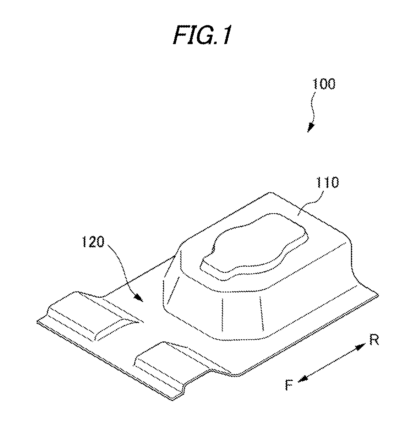
[0023]A press-forming apparatus 1 according to one exemplary embodiment is configured to form a rear floor panel 100 of a vehicle by a single stroke. The rear floor panel 100 includes a spare tire pan 110 provided on a rear side thereof and an convex-concave 120 extending in a vehicle width direction and provided between the spare tire pan 110 and a front side thereof, as illustrated in FIG. 1.

[0024]The rear floor panel 100 is attached to a vehicle body in a state where an upper surface of the spare tire pan 110 illustrated in FIG. 1 is directed toward a lower side of the vehicle.

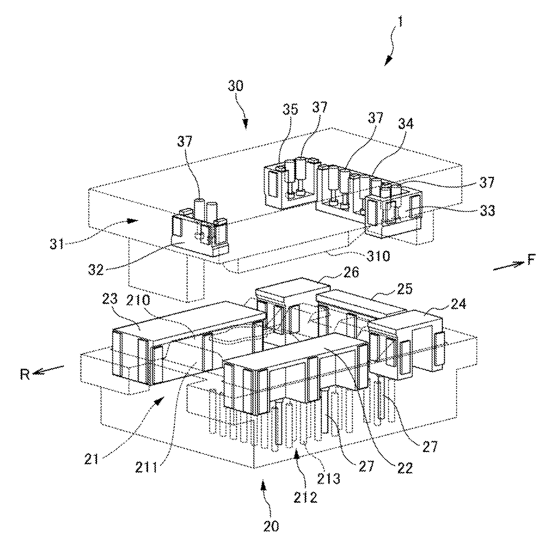
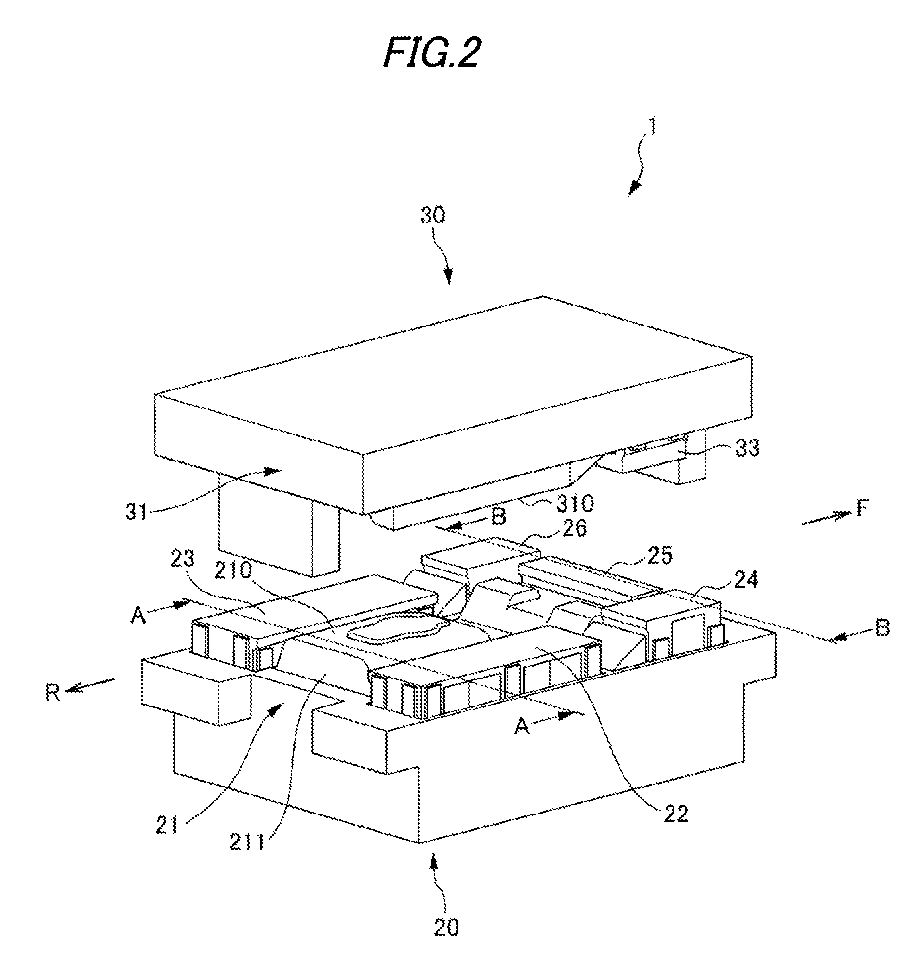
[0025]FIG. 2 is a view illustrating a configuration of the pre...


PUM

PropertyMeasurementUnit
Lengthaaaaaaaaaa
Widthaaaaaaaaaa

Abstract

A workpiece is press-formed into a press-formed product in a single stroke using a punch and a die by grasping a first portion of the workpiece by a blank holder at a first timing in the single stroke, and grasping a second portion of the workpiece which is different form the first portion by the blank holder at a second timing in the single stroke which is different from the first timing.

Description

BACKGROUND OF THE INVENTION[0001]1. Field of the Invention[0002]The present invention relates to a press-forming method and a press-forming apparatus. More specifically, the present invention relates to a press-forming method and a press-forming apparatus capable of forming a workpiece by a punch and a die in a state where the workpiece is grasped by a blank holder.[0003]2. Related Art[0004]Conventionally, a draw-forming of a workpiece such as a sheet metal panel has been carried out by a punch and a die in a state where an end of the workpiece is grasped by a blank holder. The end of the workpiece grasped by the blank holder is unnecessary in a final product. Accordingly, a trimming process for cutting the end is carried out after a draw-forming process.[0005]Herein, as the portion which is cut away by the trimming process (so-called a waste-margin) increases, the yield of material decreases. For example, in a case of forming a rear floor panel of a vehicle which includes a spare t...

Claims


Application Information

Patent Timeline
IPC IPC(8): B21D11/00
CPCB21D22/22
Inventor NAKAMURA, TSUYOSHIWAKAYAMA, NAOHIRO
Owner HONDA MOTOR CO LTD
Why Eureka
Try Eureka