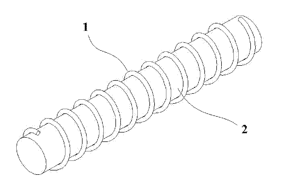
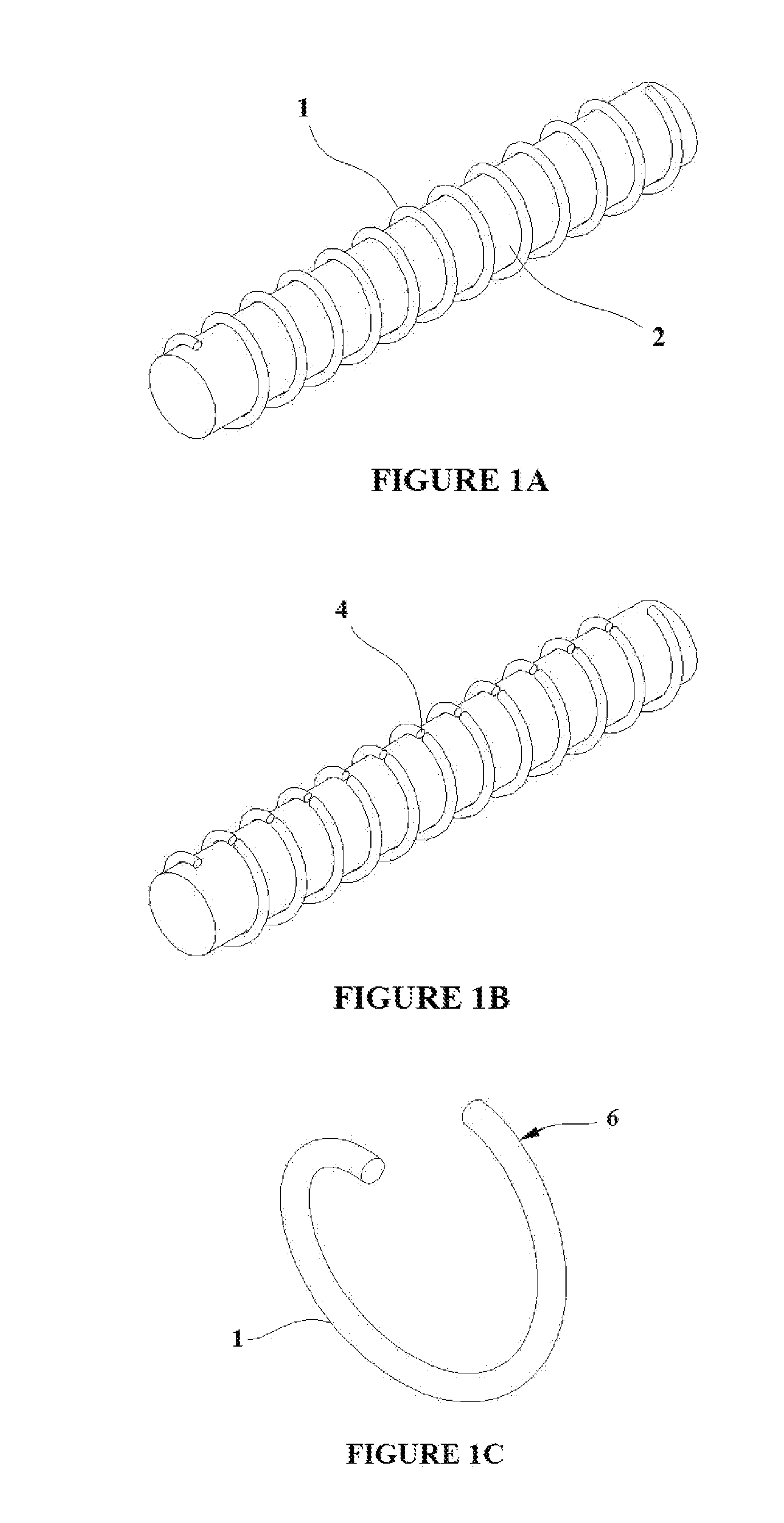
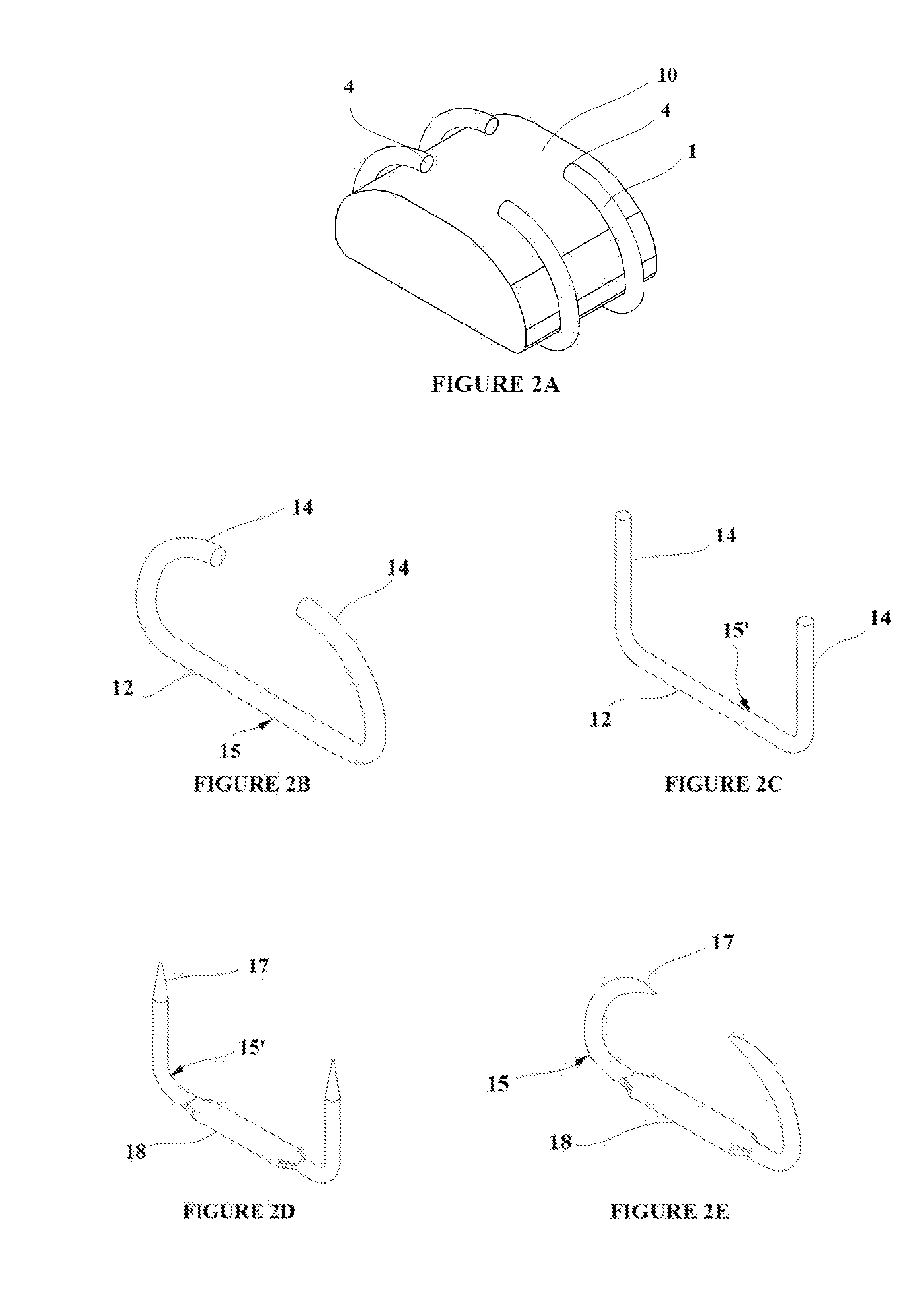
Apparatus and method for tissue adhesion

a tissue adhesion and applicator technology, applied in the field of tissue modification and wound closure, can solve the problems of difficulty for some operators in tying and placing a proper knot in the suture, high degree of experience and manual dexterity, and each of the technologies has notable limitations

Active Publication Date: 2012-12-27
MICROKOLL
View PDF13 Cites 9 Cited by
  • Summary
  • Abstract
  • Description
  • Claims
  • Application Information

AI Technical Summary

Benefits of technology

[0010]Embodiments employing joined flexible base material having tissue engagement elements extending from both sides of the resulting pad allow for certain wound closure methods. Similarly, folding of pads having tissue engagement members engaged in a tissue layer with adhesive bonding of the folded pad provides an alternative method for wound closure.
[0011]Embodiments employing a perforated or porous base layer allow drainage of a closed wound and a compressible foam pad overlaying the shape memory engagement elements insulates from premature activation.
[0012]Embodiments employing tissue capture elements having length, l, with shape memory properties activated by temperature allows application of electromagnetic energy to the tissue capture elements having a frequency, f, tuned to the length for activation of the tissue capture elements.

Problems solved by technology

Each of these technologies has notable limitations.
For example, a suture may be deployed into an incision, but tying and placing a proper knot in the suture may require a high degree of experience and manual dexterity and may be difficult for some operators.
If the suture knot is not properly tightened, the incision may bleed or be otherwise compromised,
Staples, however, may not always completely close the wound and may not be re-adjusted, if such adjustment is required, after deployment.
In addition, staples tend to be deployed in discrete locations due to their bulk and may produce concentrated stress and strain points within tissue adjacent the deployed staples.
Biological adhesives may be applied into a wound, but the presence of blood will often hinder an effectiveness of the adhesion strength between the adhesive and tissue.
Also, biological tissue adhesives often tend to be rigid after they have cured, so as to cause stiffness at the point of contact and reduce flexibility of the wound when stress is applied thereto.
Such a relatively stiff joint may even fracture or crack when stressed causing the wound to reopen and hemorrhaging to occur.

Method used


Image

  • Apparatus and method for tissue adhesion
  • Apparatus and method for tissue adhesion
  • Apparatus and method for tissue adhesion

Examples


first embodiment

[0049]A method for formation and use of an SMP tissue capture element embodiment with the deployment-engagement-removal activation capabilities that have previously been described is shown in FIGS. 9A-9E. FIG. 9A shows a SMP composite sheet 33 formed from two SMP material sheets 20 and 32 with transition temperatures Ttrans1 and Ttrans2 respectively. The composite sheet 33 is processed as previously described such that each sheet is in pre-strained states 20′ and 32′. A pattern for a tissue capture element is cut along the cut lines 26 which provide shaping for a flange 18 as previously described for the first embodiment and pointed tips for piercing tissue. The resulting tissue capture element 40 is shown in FIG. 9B. The tissue capture element 40 is flat as cut from the composite sheet, and must be suitably configured to facilitate penetration into the target tissue. To accomplish this, the SMP tissue capture element can be placed over a form and heat applied to the transition area...

embodiment 46

[0050]FIG. 10A shows another embodiment of a tissue capture element cut from a duel SMP composite sheet such as sheet 33 shown in FIG. 7A having a pointed tip for piercing tissue and a base 43 comparable in function to the flange of the prior embodiment for enhanced retention in a mold substrate as will be describe subsequently. The composite tissue capture element 42 shown in the deployment state is comprised of two pre-strained SMP polymer materials 20′ and 32′ (Ttrans1 and Ttrans2 respectively) which allow for the deployment-engagement-removal state transitions which have been previously described. The SMP composite shape memory element is shown above Trans1 in the engagement state 42′ in FIG. 10B with the SMP material 20′ transitioned to its unstrained state 20. The SMP composite shape memory element is shown above Trans2 in the removal state 42″ in FIG. 10B with the SMP material 32′ transitioned to its unstrained state 32. FIG. 11A shows a double version 44 of the composite tis...


PUM


Abstract

Shape memory tissue engagement elements (15) are created using shape memory alloys or shape memory (SM) composite sheets (33, 36) with one or more SM material sheets (20, 32). Arrays of the tissue engagement elements may then be inserted or molded into flexible base materials forming pads for tissue engagement. In certain embodiments, the composite sheets incorporate two SM material layers (20, 32) having differing transition temperatures to allow activation of one layer for tissue engagement and activation of the second layer for tissue release. In exemplary embodiments, insertion of interconnected tissue engagement elements (46) into a base layer (19) with slots (48) provides a completed pad array. In alternative exemplary embodiments, vacuum forming of composite sheets (51) with cutting of corrugated sides (53) to form tissue engagement elements allow production of complete arrays of tissue engagement elements. Overmolding the arrays with a flexible base material (19) provides a completed pad.

Description

REFERENCE TO RELATED APPLICATIONS[0001]This application claims the priority of U.S. Provisional Application Ser. No. 61 / 313,036 filed on Mar. 11, 2010 by Steven Craig Anderson entitled Apparatus and Method for Tissue Adhesion, the disclosure of which is incorporated herein by reference.BACKGROUND[0002]1. Field[0003]This application relates generally to the field of tissue modification and wound closure and more particularly to potential configurations, manufacturing methods, shape memory activation methods, and treatment applications for tissue capture elements and flexible substrate material embodiments for a substrate supporting a plurality of substantially parallel shape memory microposts for insertion into tissue adjacent a wound or tissue modification site with activation of the shape memory properties of the microposts to deform for adherence to the tissue.[0004]2. Related Art[0005]Tissue adhesion devices and methods have a wide variety of useful indications. For example, ther...

Claims


Application Information

Patent Timeline
Patent Type & Authority Applications(United States)
IPC IPC(8): B21D43/28
CPCA61B17/064A61B17/0644A61B2017/00526A61B2017/00867C08L2201/12A61B2017/0641A61B2017/0647A61L2400/16A61B2017/00871
Inventor ANDERSON, STEVEN CRAIG
Owner MICROKOLL
Why Eureka
Try Eureka