Nasal cavity insertion device fixture and nasal cavity insertion device set including the same

a technology for insertion devices and nasal cavities, which is applied in the direction of tube connectors, other medical devices, nursing devices, etc., can solve the problem that patients with sleep disorders are not treated sufficiently

Active Publication Date: 2012-12-27
SEVEN DREAMERS LAB
View PDF9 Cites 4 Cited by
  • Summary
  • Abstract
  • Description
  • Claims
  • Application Information

AI Technical Summary

Benefits of technology

[0013]It is an object of the present invention to provide a nasal cavity insertion device fixture and a nasal cavity insertion device set including the same, whereby the displacement or the detachment of a nasal cavity insertion tube can be prevented during the sleep of a patient of sleep disorder.
[0065]According to the aforementioned configuration, air permeability between the inside and the outside of a nasal passage can be reliably achieved through the through hole / holes by forming the base end section of the device in a tapered shape even when the base end section is disposed while covering a nasal passage.

Problems solved by technology

Incidentally, in the aforementioned methods, it has been concerned that a patient of sleep disorder is not treated sufficiently due to the displacement or the detachment of the nasal cavity insertion tube during the sleep of the patient of sleep disorder.

Method used


Image

  • Nasal cavity insertion device fixture and nasal cavity insertion device set including the same
  • Nasal cavity insertion device fixture and nasal cavity insertion device set including the same
  • Nasal cavity insertion device fixture and nasal cavity insertion device set including the same

Examples


first embodiment

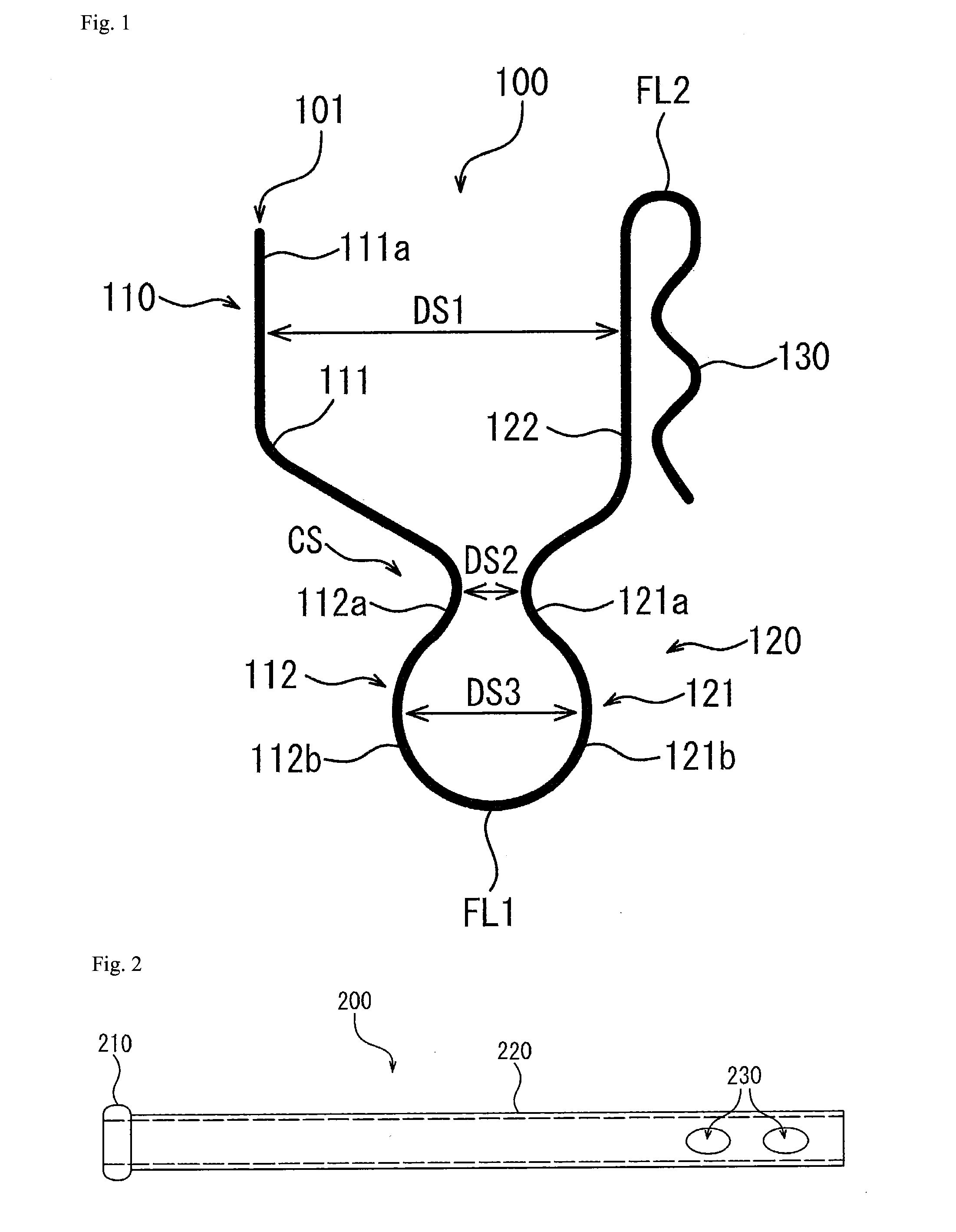
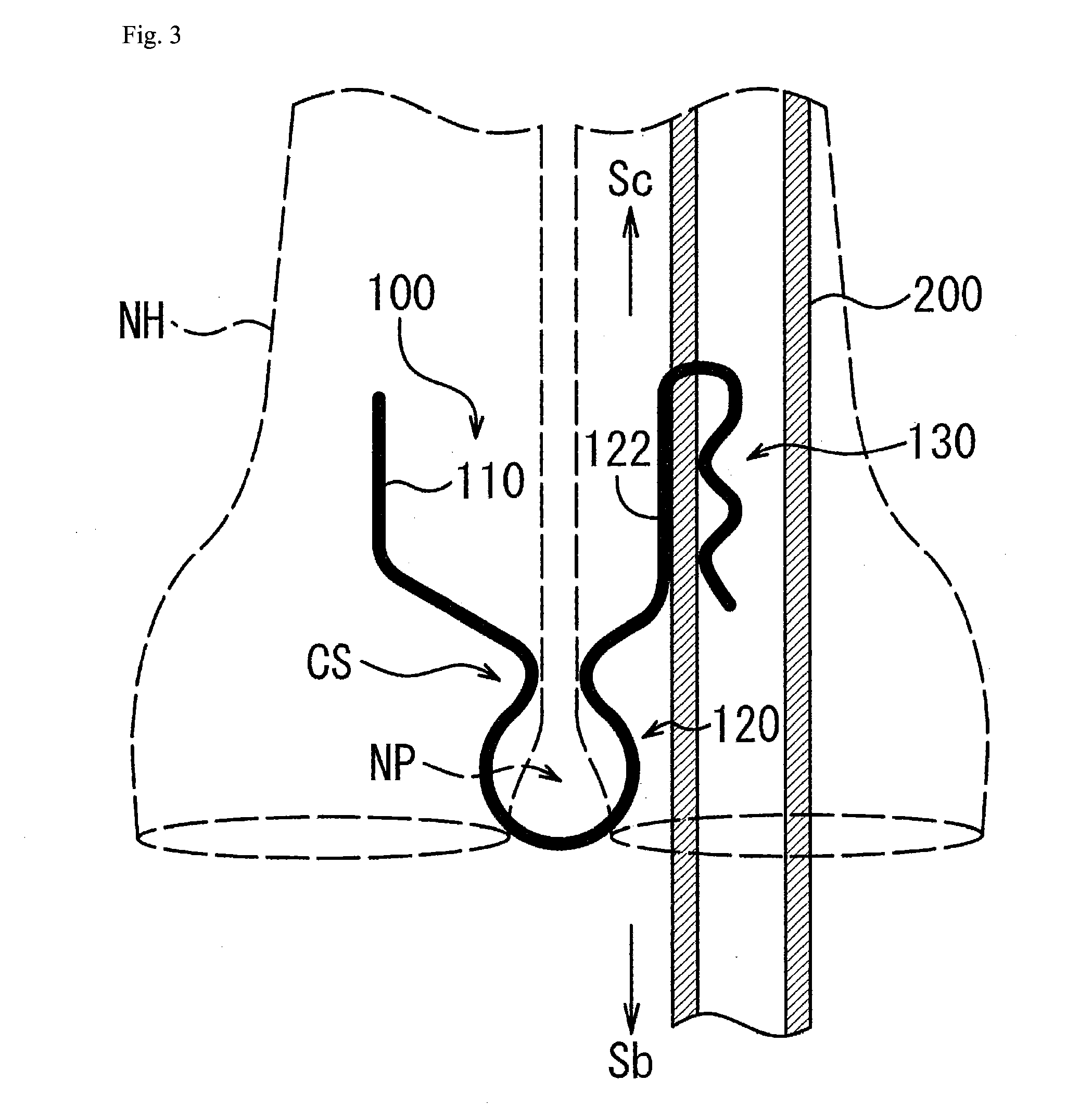
[0131]A nasal cavity insertion tube fixture (hereinafter simply referred to as a fixture on an as-needed basis) 100 according to a first embodiment of the present invention is a fixture for fixing a nasal cavity insertion tube 200 (see FIG. 2) to a bridge of the nose NP (see FIG. 3) and is formed with a wire rod 101 as shown in FIG. 1.

[0132]It should be noted in the present embodiment that the nasal cavity insertion tube 200 is formed with a main body part 220, a tip portion 210 and openings 230 as shown in FIG. 2. The main body part 220 is a tubular body made of silicone resin. As shown in FIG. 2, the tip portion 210 has a ring shape and is disposed on a tip of the main body part 220. Two openings 230 are formed in the base end side section of the main body part 220 while penetrating through the sidewall of the main body part 220.

[0133]For easy explanation of the fixture 100, the wire rod 101 is hereinafter assumed to be formed by mainly three parts, i.e., a first wire rod part 110...

second embodiment

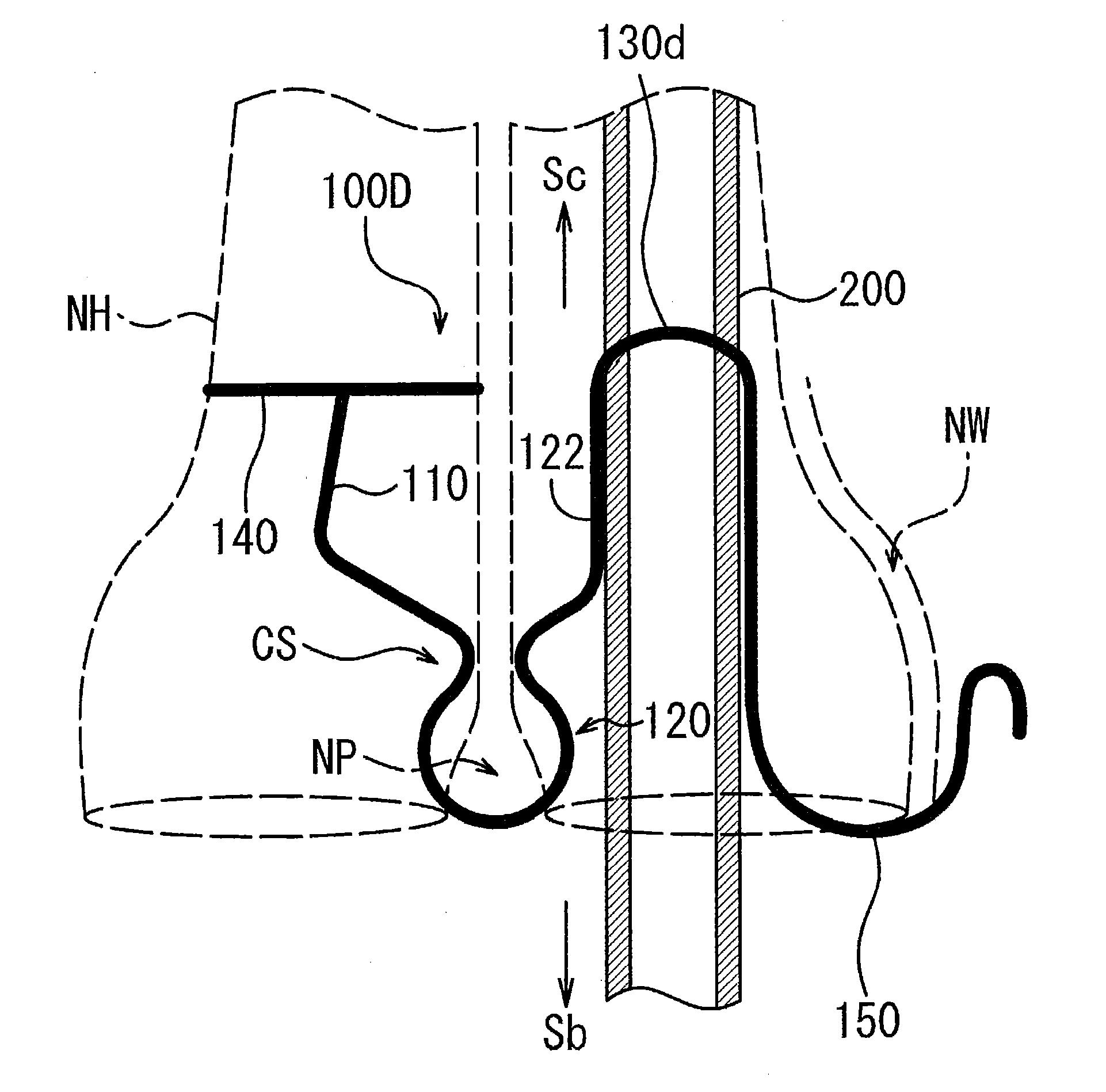
[0182]Similarly to the fixture 100 according to the first embodiment, a fixture 100D according to a second embodiment of the present invention is formed by the wire rod 101. Further, as shown in FIG. 9, the fixture 100D is mainly formed by the first wire rod part 110, the second wire rod part 120, a third wire rod part 130d, a fourth wire rod part 150 and the second circular wire rod part 140.

Configuration of Fixture

[0183]The first wire rod part 110 and the second wire rod part 120 are respectively the same as the first wire rod part 110 and the second wire rod part 120 according to the first embodiment. The second circular wire rod part 140 is the same as the second circular wire rod part 140 described in the variation (C) of the first embodiment.

[0184]The third wire rod part 130d and the fourth wire rod part 150, both of which do not exist in the fixtures 100, 100A, 100B and 100C according to the first embodiment and the variations thereof, will be hereinafter explained in detail...

third embodiment

[0192]As shown in FIG. 14(a), a nasal cavity insertion device set 300J according to a third embodiment of the present invention includes a fixture 100J and a nasal cavity insertion tube 200J. It should be noted that the fixture 100J is similar to the fixture 100 according to the aforementioned first embodiment, and therefore, explanation thereof will be hereinafter omitted.

Configuration of Tube

[0193]The nasal cavity insertion tube 200J is a tube made of silicone rubber and has a length roughly the same as the distance from the entrance of a nasal passage to a pharynx. It should be noted that the fixture 100J can be attached to the base end side of the nasal cavity insertion tube 200J. Further, the nasal cavity insertion tube 200J has four thin portions 210J formed at predetermined intervals on the sidewall of the base end side section thereof. It should be herein noted that the example of forming the thin portions 210J has been explained. However, the present invention is not limit...


PUM


Abstract

A fixture is provided for attachment to a device to be inserted into a nasal cavity. Further, the fixture is a nasal cavity insertion device fixture formed of a wire rod. The fixture includes a first wire rod part, a second wire rod part, and a third wire rod part. The second wire rod part is connected to the first wire rod part and formed by folding back the wire rod so as to be opposed to the first wire rod part. The third wire rod part is connected to the second wire rod part and formed by bending the wire rod so as to be disposed oppositely to a side of the second wire rod part facing the first wire rod part.

Description

BACKGROUND OF THE INVENTION[0001]1. Field of the Invention[0002]The present invention relates to a nasal cavity insertion device fixture and a nasal cavity insertion device set including the same.[0003]2. Description of the Related Art[0004]Patients of obstructive sleep apnea syndrome (OSAS) intermittently repeat a temporally suffocated state (apnea, infrequent breathing) while the pharynx of the upper respiratory tract is obstructed due to a complication of muscle relaxation and obesity and the like during sleep. Therefore, patients of OSAS are suffered from hypertension or disorders in brain blood vessels and cardiac blood vessels. Further, patients of OSAS cannot sleep sufficiently, and therefore, tend to feel drowsy in the daytime and / or tend to lack of concentration or vitality in the daytime. Yet further, when driving a car, patients of OSAS have high chances of causing an accident, a serious accident or the like due to falling asleep at the wheel.[0005]On the other hand, simi...

Claims


Application Information

Patent Timeline
Patent Type & Authority Applications(United States)
IPC IPC(8): A61F5/56
CPCA61F5/56A61M2210/0618A61M16/0488A61M16/0461A61M39/10A61M31/00A61M29/00
Inventor YAMADA, HIROSHITANIGUCHI, YOSUKEHATTORI, YOSHIKIHIOKI, KENJISAKANE, SHINICHI
Owner SEVEN DREAMERS LAB
Why Eureka
Try Eureka