
Reinforcing method and arrangement for foldable furniture

a folding furniture and reinforcement method technology, applied in the direction of dismountable cabinets, rod connections, chairs, etc., can solve the problems of insufficient light-duty folding chairs or tables, insufficient leg supports, and insufficient support for folding chairs

Inactive Publication Date: 2012-12-27
TSAI FRANK
View PDF4 Cites 2 Cited by
  • Summary
  • Abstract
  • Description
  • Claims
  • Application Information

AI Technical Summary

Benefits of technology

[0008]Another advantage of the invention is to provide a foldable furniture object which comprises a top unit; a foldable frame assembly which includes a frame support unit and a leg support unit; and a reinforcing arrangement connecting the leg support unit to the frame support unit in a foldable and secure manner while reinforcing the junction between the frame support unit and the leg support unit.
[0009]Another advantage of the invention is to provide a foldable furniture object which comprises a top unit; a foldable frame assembly which includes a frame support unit and a leg support unit; and a reinforcing arrangement connecting the leg support unit to the frame support unit in such a manner that the junction between the frame support unit and the leg support unit is reinforced and a maximum unfolding angle of the leg support unit relative to the frame support unit is defined.
[0010]Another advantage of the invention is to provide a foldable furniture object which comprises a top unit; a foldable frame assembly which includes a frame support unit and a leg support unit; and a reinforcing arrangement connecting two leg members of the leg support unit in a foldable and secure manner while reinforcing the junction between the two leg members.
[0011]Another advantage of the invention is to provide a foldable furniture object which comprises a top unit; a foldable frame assembly which includes a frame support unit and a leg support unit; and a reinforcing arrangement connecting two leg members of the leg support unit in such a manner that the movement of the two leg members are guided and the joint portion of the two leg members are reinforced.
[0012]Another advantage of the invention is to provide a reinforcing arrangement for reinforcing a joint portion between two support units of a foldable furniture object which comprises two mounting units complimentary to and engaging with each other to guide the movement of the two support units while reinforcing the joint portion.

Problems solved by technology

However, this kind of support has several drawbacks.
First, the support is not strong and cannot be used for medium to heavy duty foldable chair or table, and may be insufficient for light duty foldable chair or table.
Second, the mounting position of the leg support is limited to the middle or upper portion of the leg support in order to provide a stable and balance frame structure.
Third, the rotational angle between two leg support units is not controllable and additional frame elements are required to restrict the rotational movement of the leg support units.
Fourth, the rivet is subject to the weight of the foldable furniture and to the weight of the object on the foldable furniture, making the rivet a breakable part of the frame structure.
Fifth, the mounting position of the leg support units is subject to direct and immediate force for supporting the foldable furniture, making the leg support units easy to deform or distort in position and hence weakening the frame structure.
Accordingly, this kind of mounting is fragile, making the foldable furniture easy to collapse.
Another common mounting arrangement includes mounting a pair of leg support units onto two sides of a furniture top unit such as a chair seat or a table top with rivets in a foldable manner, which is insufficient and uncontrollable.
The leg support units themselves cannot be used to provide sufficient support to the furniture while specific and dedicate frame construction is required to provide support for the furniture.
In other words, this kind of mounting method for foldable furniture is not only weak but also complicate and costly.

Method used


Image

  • Reinforcing method and arrangement for foldable furniture
  • Reinforcing method and arrangement for foldable furniture
  • Reinforcing method and arrangement for foldable furniture

Examples


Embodiment Construction

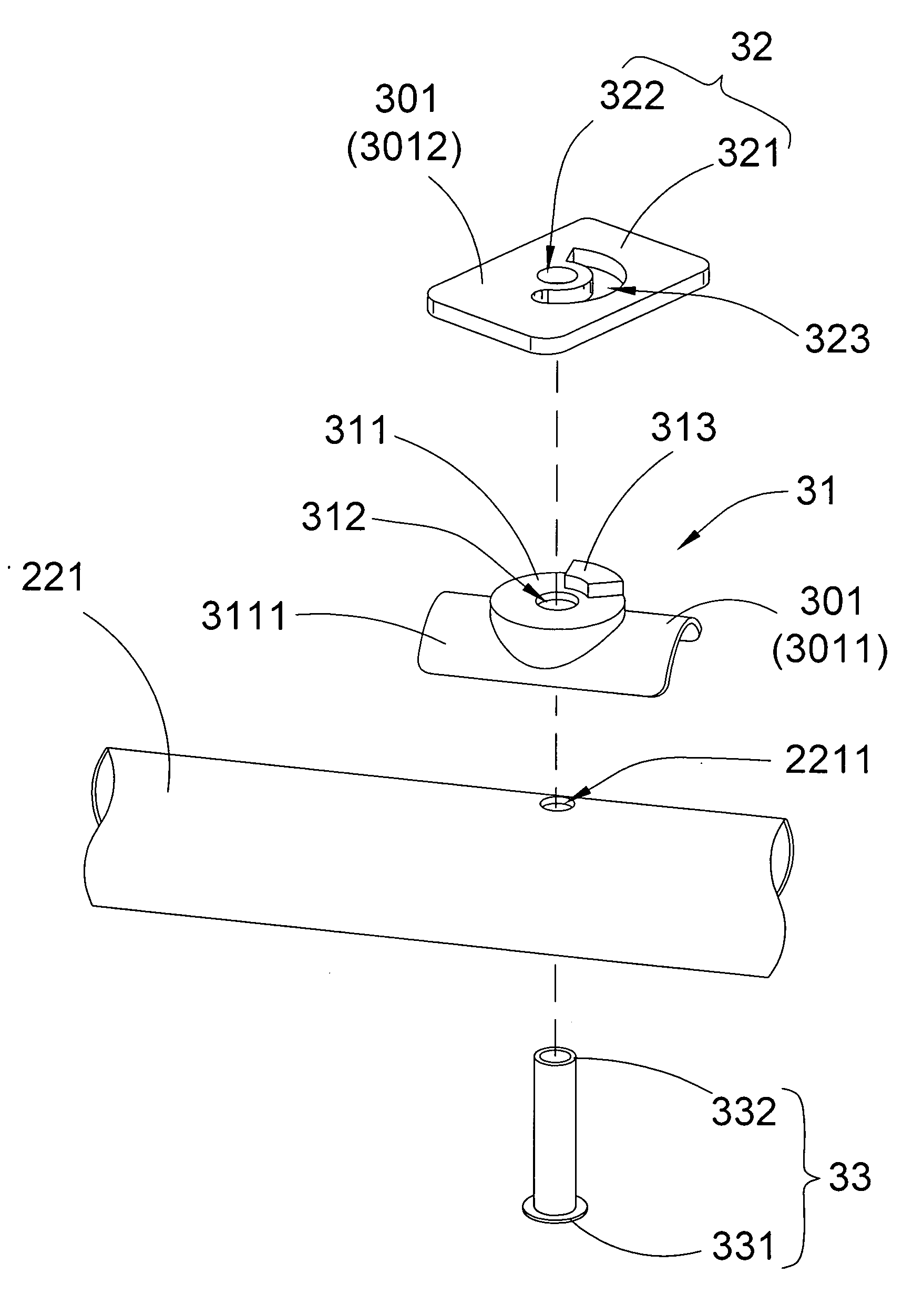
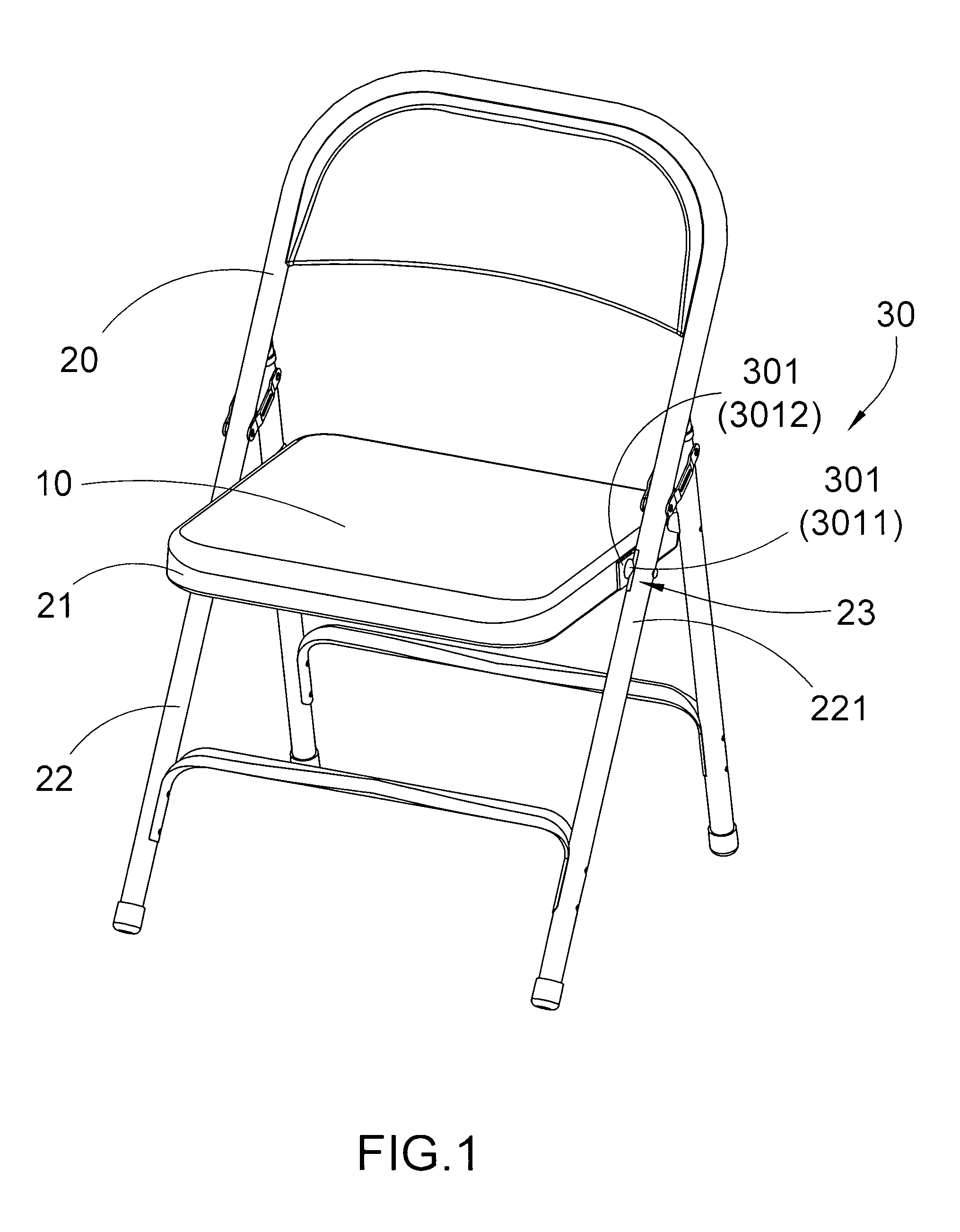
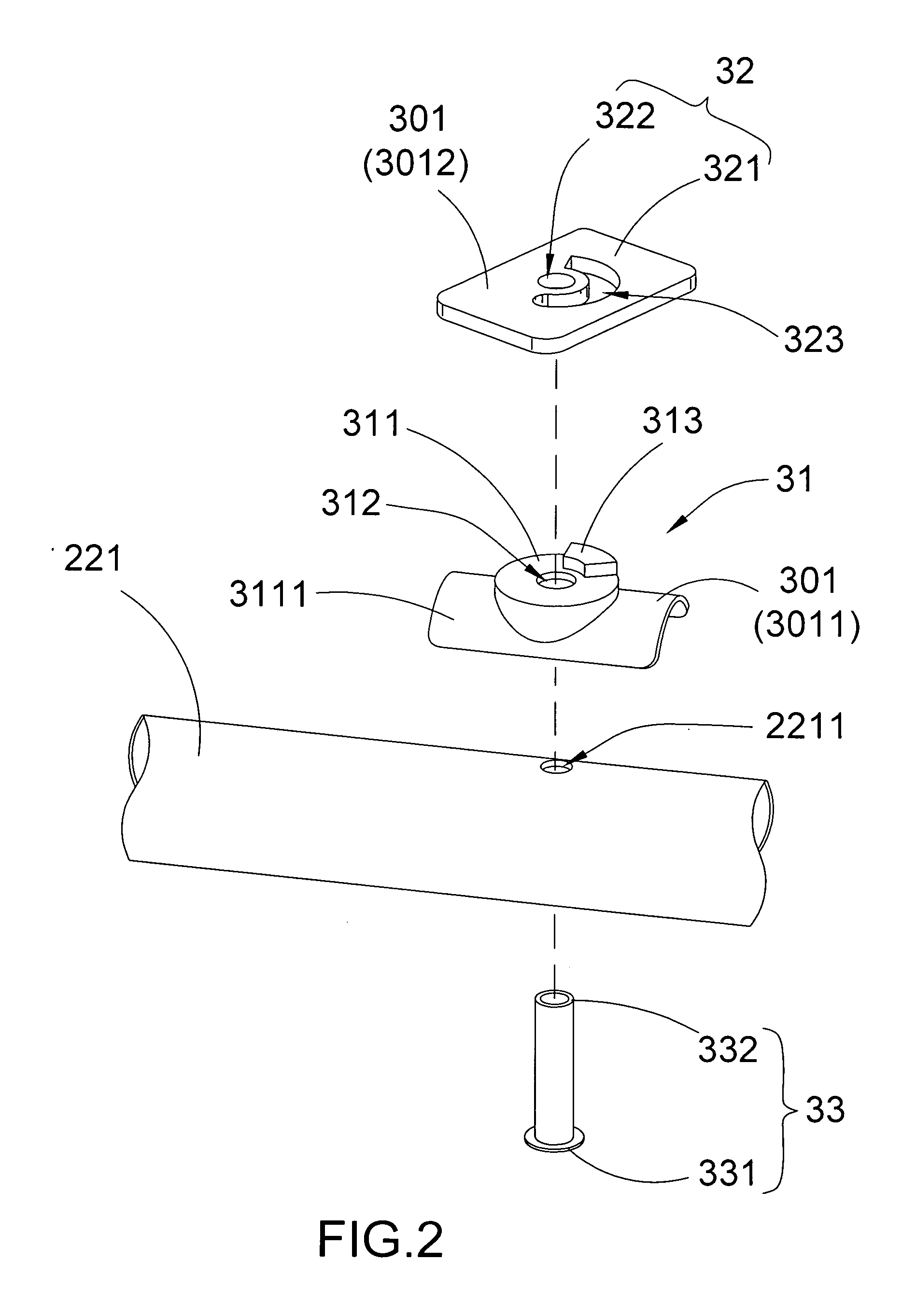
[0049]Referring to FIGS. 1 to 6 of the drawings, a foldable furniture object according to the preferred embodiment of the present invention is illustrated. The foldable furniture object includes a top unit 10, a foldable frame assembly 20 and a reinforcing arrangement 30.

[0050]The foldable furniture object may be a foldable table or a foldable chair, or the like. Accordingly, the top unit 10 may be a table top, a chair seat or the like which is supported by the foldable frame assembly 20 in a foldable manner and reinforced through the reinforcing arrangement 30. The top unit 10 can be a wooden top unit, a plastic top unit, or a metallic top unit.

[0051]The foldable frame assembly 20 comprises a frame support unit 21 connected to the top unit 10, and a leg support unit 22 connected to the frame support unit 21 in a foldable manner such that the leg support unit 22 is capable of being folded to a folded position and unfolded to a unfolded position respectively. In particular, the leg s...


PUM

PropertyMeasurementUnit
spread forceaaaaaaaaaa
angleaaaaaaaaaa
areaaaaaaaaaaa

Abstract

A reinforcing arrangement for reinforcing a joint portion between two support units of a foldable furniture object, comprising a first mounting unit which comprises a first mounting body and a first guiding member outwardly protruded from the first mounting body mounting on the first support unit; a second mounting unit which comprises a second mounting body and a second guiding member or a second guiding groove complimentary to and moveably engaging with the first mounting unit to define a maximum extending angle of movement, thereby the first and second support unit are guided to lock into position at an unfolded position at the maximum extending angle and to unlock at a folded position; and a connecting unit pivotally connecting the first support unit and the second support unit between which the two mounting units are positioned, thereby the joint portion is reinforced.

Description

BACKGROUND OF THE PRESENT INVENTION[0001]1. Field of Invention[0002]The present invention relates to foldable furniture such as foldable chair and foldable table, and more particularly to a reinforcing method and arrangement for foldable furniture arranged for connecting at least one tube-like leg support unit with another leg support unit or another frame support unit in a secure, controllable and foldable manner while folding movement of the tube-like leg support unit is guidable and controllable and the connecting junction are reinforced.[0003]2. Description of Related Arts[0004]Conventional foldable furniture, such as foldable chair and foldable table, usually includes a furniture top unit and a frame body to support the top unit in which four leg support units are provided and mounted in a foldable manner. Light duty foldable furniture usually has two pairs of leg support units and a plurality of rivets for mounting the leg support units. For example, each of the leg support un...

Claims


Application Information

Patent Timeline
Patent Type & Authority Applications(United States)
IPC IPC(8): F16C11/10B23P11/00A47C4/04F16C11/04A47B43/00A47B3/08
CPCA47B3/02A47C4/20A47C4/24A47C4/48Y10T403/16Y10T403/32254Y10T403/32606Y10T29/49826A47C4/04Y10T29/4962E05D11/06E05D3/02A47C4/00
Inventor TSAI, FRANK
Owner TSAI FRANK
Learn More