Battery charging system for vehicle and battery charge controller in the same
- Summary
- Abstract
- Description
- Claims
- Application Information
AI Technical Summary
Benefits of technology
Problems solved by technology
Method used
Image
Examples
first embodiment
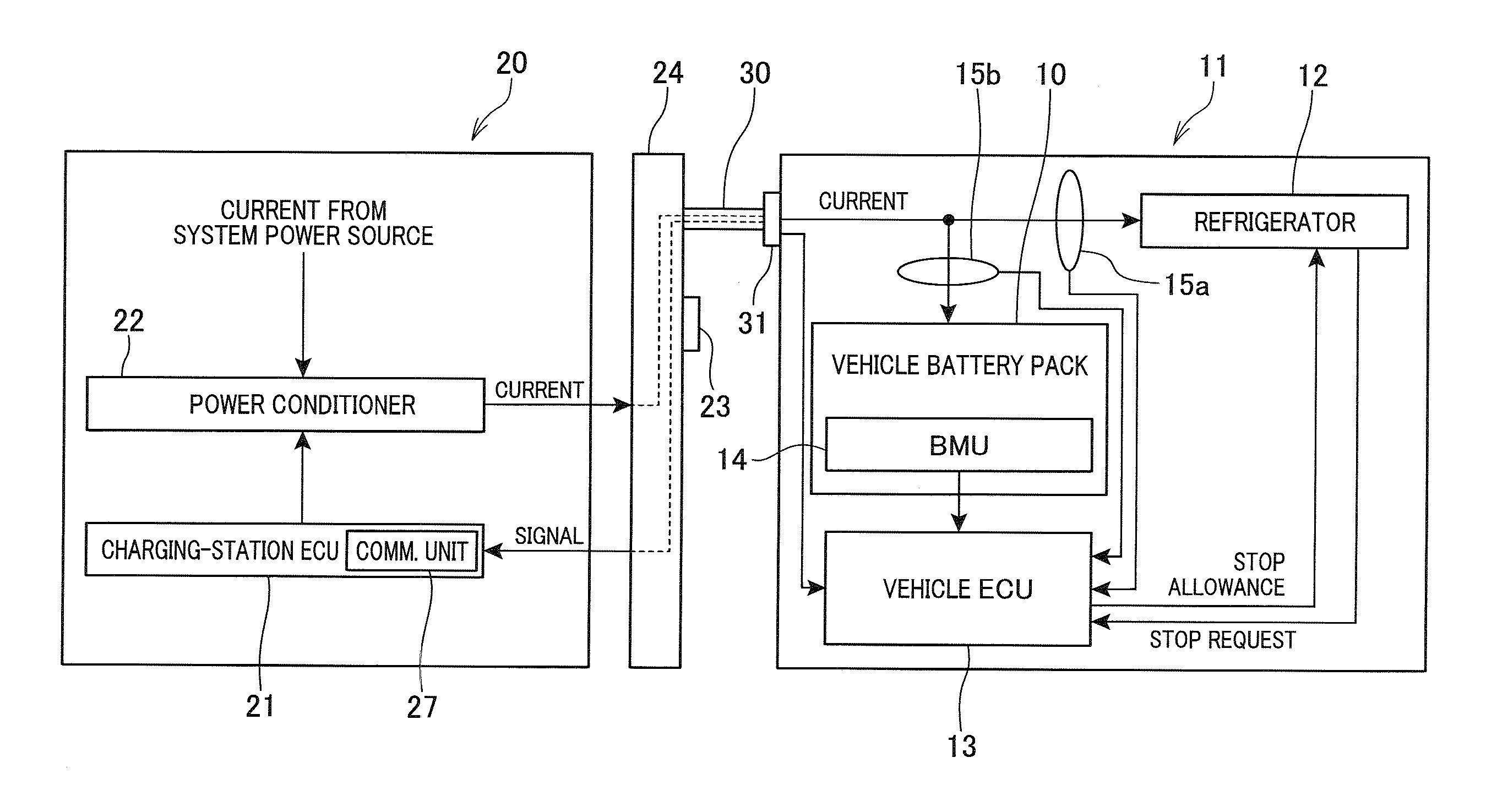
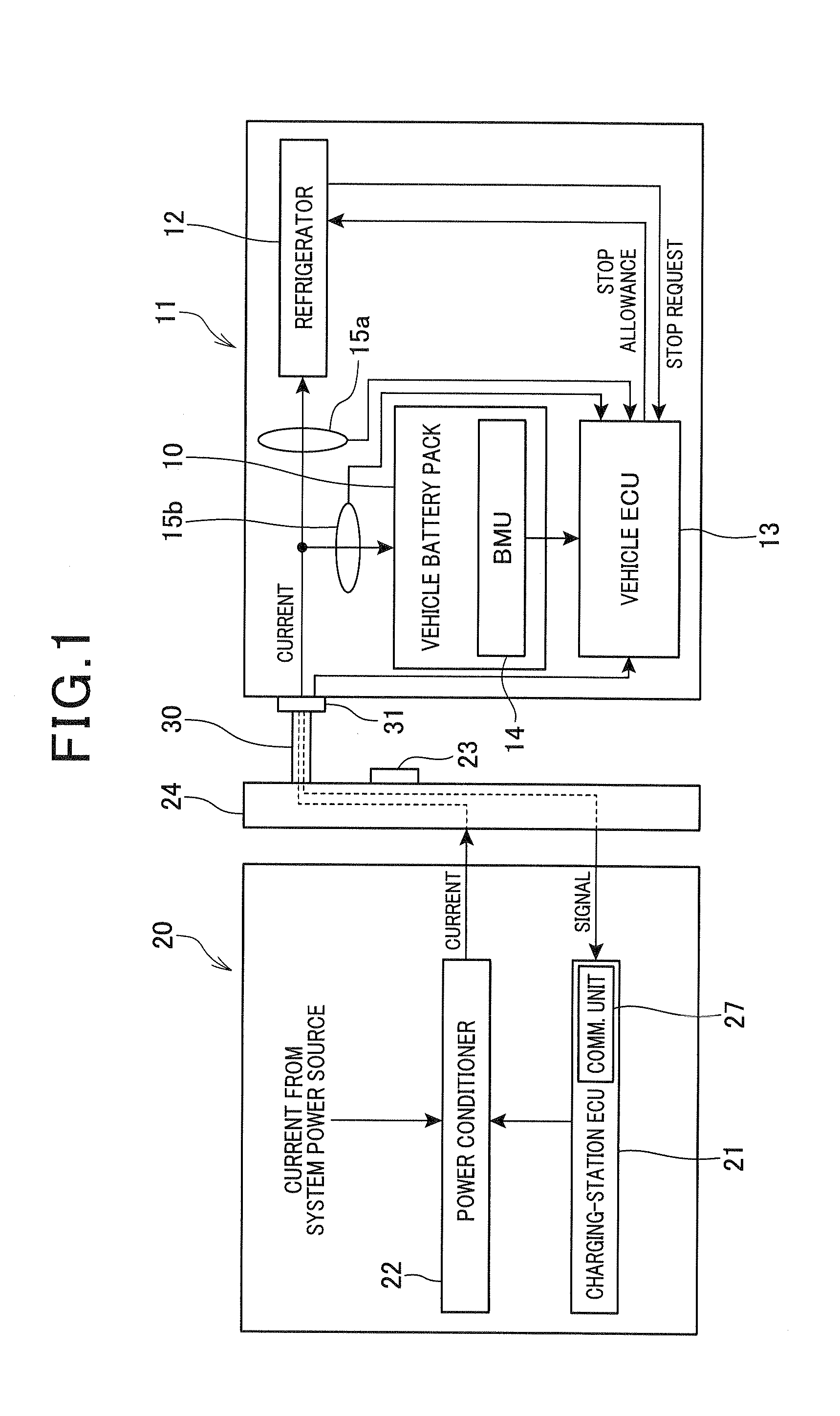
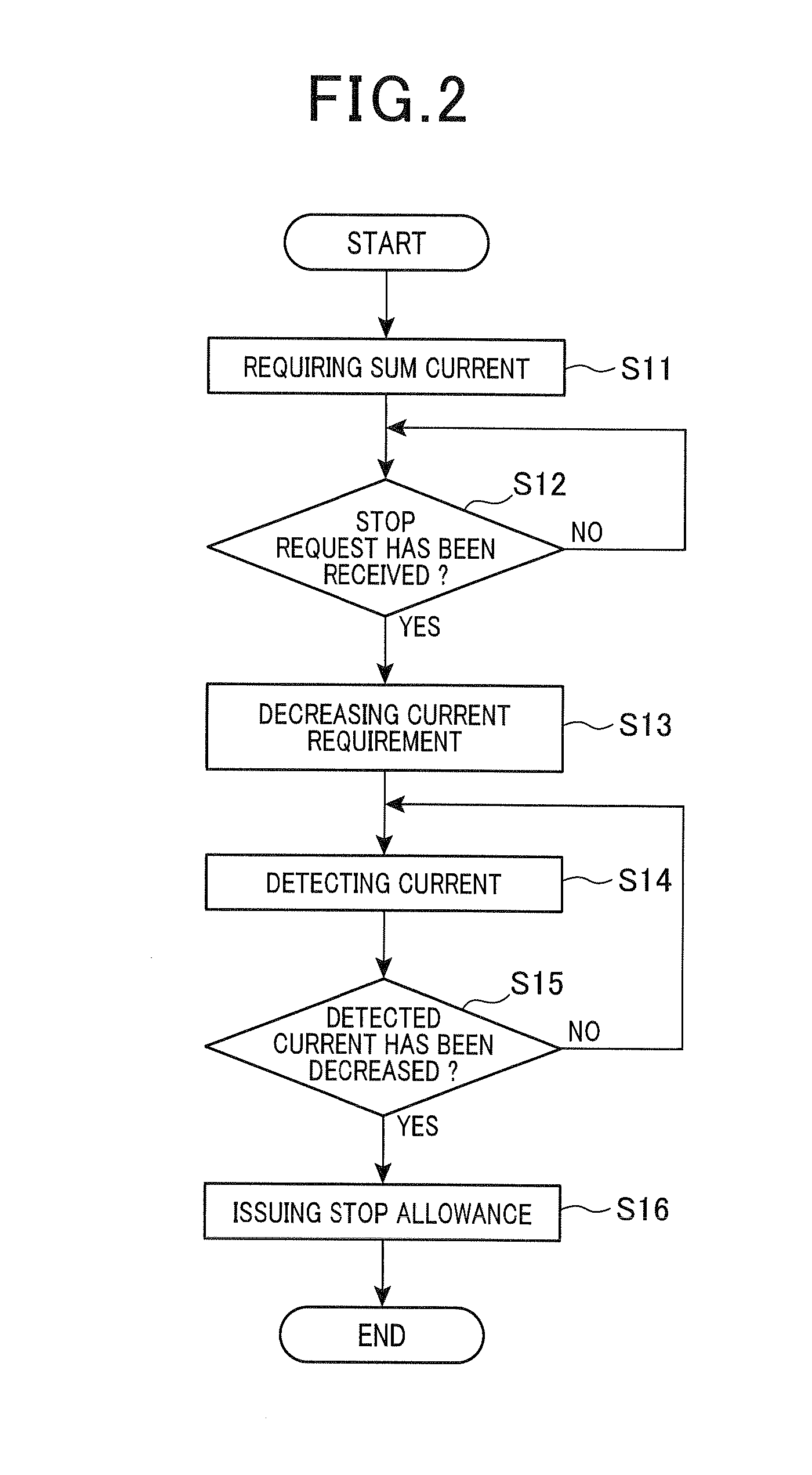
[0020]There will now be explained a battery charging system 11 for a vehicle in accordance with a first embodiment of the present invention with reference to FIGS. 1, 2. FIG. 1 schematically shows a block diagram of the battery charging system 11 and a charging station 20. The battery charging system 11 is adapted to charge a vehicle battery pack 10 with an electrical current supplied from an external power source, such as the charging station 20, to a vehicle having the battery charging system 11 mounted therein. In the present embodiment, the vehicle is a refrigerated vehicle equipped with a refrigerator 12. The battery charging system 11 includes the vehicle battery pack 10, an Electronic Control Unit (ECU) 13 (hereinafter referred to as a vehicle ECU), the refrigerator 12, a first current detector 15a, and a second current detector 15b.
[0021]The vehicle battery pack 10 can be charged with a direct electrical current and can discharge accumulated electrical power. The vehicle ba...
second embodiment
[0047]There will now be explained a battery charging system 11 for a vehicle in accordance with a second embodiment of the present invention with reference to FIGS. 1, 3. Only differences of the second embodiment from the first embodiment will be explained. FIG. 1 is also a block diagram of a battery charging system and a charging station in accordance with the second embodiment.
[0048]FIG. 3 shows a flowchart of a charging process performed by the vehicle ECU 13 in accordance with a second embodiment. The charging process is started with a start operation performed by operating the operating switch 23 immediately after electrical connection of the charging cable 30 to the vehicle during operation of the refrigerator 12.
[0049]In step S21, the vehicle ECU 13 requires the charging-station ECU 21 to supply a sum current that is a sum of a current for charging the vehicle battery pack 10 and a current for driving the refrigerator 12. Subsequently, the process proceeds to step S22, where ...
third embodiment
[0052]There will now be explained a battery charging system 11 for a vehicle in accordance with a third embodiment of the present invention with reference to FIGS. 1, 4. Only differences of the third embodiment from the first or second embodiment will be explained. FIG. 1 is also a block diagram of a battery charging system and a charging station in accordance with the third embodiment.
[0053]FIG. 4 shows a flowchart of a charging process performed by the vehicle ECU 13 in accordance with a third embodiment. The charging process is started with a start operation performed by operating the operating switch 23 immediately after electrical connection of the charging cable 30 to the vehicle during operation of the refrigerator 12.
[0054]In step S31, the vehicle ECU 13 requires the charging-station ECU 21 to supply a sum current that is a sum of a current for charging the vehicle battery pack 10 and a current for driving the refrigerator 12. Subsequently, the process proceeds to step S32, ...
PUM
 Abstract
Description
Claims
Application Information
 - R&D
- Intellectual Property
- Life Sciences
- Materials
- Tech Scout
- Unparalleled Data Quality
- Higher Quality Content
- 60% Fewer Hallucinations
Browse by: Latest US Patents, China's latest patents, Technical Efficacy Thesaurus, Application Domain, Technology Topic, Popular Technical Reports.
© 2025 PatSnap. All rights reserved.Legal|Privacy policy|Modern Slavery Act Transparency Statement|Sitemap|About US| Contact US: help@patsnap.com


