Evaporation control device used in refrigerating system

A control device and refrigeration system technology, which is applied in the direction of refrigerators, refrigeration components, refrigeration and liquefaction, etc., can solve the problems of poor response sensitivity, poor energy saving effect, weak control function, etc., to improve response sensitivity, reduce running time, reduce The effect of load fluctuations

Inactive Publication Date: 2011-07-06
DANFOSS SHANGHAI AUTOMATIC CONTROLS
View PDF0 Cites 9 Cited by
  • Summary
  • Abstract
  • Description
  • Claims
  • Application Information

AI Technical Summary

Problems solved by technology

The existing evaporation control device cannot realize the pulse control of the anti-dew heating wire, and usually adopts a 24-hour full-on working mode, which consumes a lot of energy
[0007] The existing evaporation controller does not have a communication function, and cannot realize the functions of centralized monitoring and remote monitoring
Even if some evaporation control devices have communication functions, they are only limited to a certain communication protocol, and different communication protocols cannot be used according to the needs of users.
[0008] Therefore, most of the evaporation control devices in the current refrigeration system cannot achieve precise temperature and pressure control at the same time, nor can they achieve centralized control, and the existing evaporation control devices have poor response sensitivity, large fluctuations in the temperature of the evaporator, and energy saving. poor effect
Existing evaporation control devices have poor scalability and weak control functions, and cannot be applied to many different occasions

Method used


Image

  • Evaporation control device used in refrigerating system
  • Evaporation control device used in refrigerating system
  • Evaporation control device used in refrigerating system

Examples


Embodiment Construction

[0049] In order to make the object, technical solution and advantages of the present invention clearer, the present invention will be described in further detail below in conjunction with specific embodiments and with reference to the accompanying drawings.

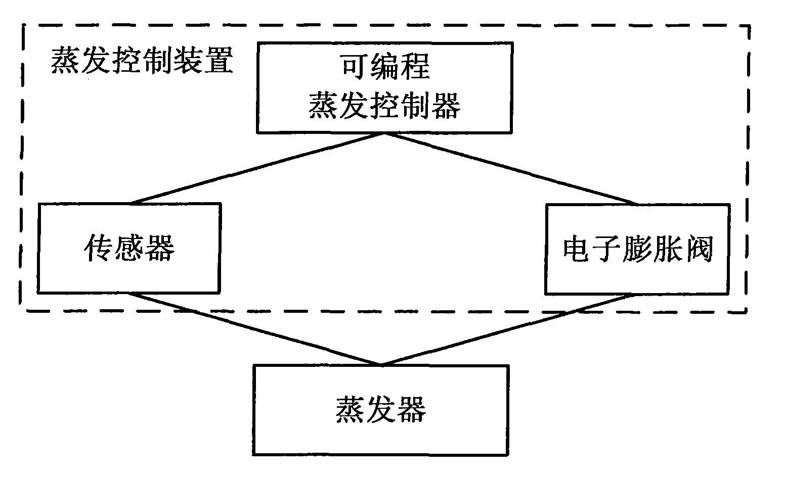
[0050] Such as figure 1 as shown, figure 1 It is a structural block diagram of an evaporation control device used in a refrigeration system provided by the present invention, and the device includes a programmable evaporation controller, an electronic expansion valve and a sensor. The programmable evaporation controller is connected to the electronic expansion valve, and the electronic expansion valve is installed on the refrigerant input pipeline of the evaporator. Among them, the sensor is used to detect the temperature and pressure inside the evaporator, and output the detected temperature and pressure signals to the programmable evaporation controller. The programmable evaporation controller is used to receive the...


PUM


Abstract

The invention discloses an evaporation control device used in a refrigerating system, comprising a programmable evaporation controller, an electronic expansion valve and a sensor, wherein, the programmable evaporation controller is connected with the electronic expansion valve, and is connected with an evaporator through the sensor; and the electronic expansion valve is arranged on a refrigerant input pipeline of the evaporator; the sensor is used for detecting the temperature and the pressure in the evaporator, and outputting the detected temperature and pressure signals to the programmable evaporation controller; the programmable evaporation controller is used for receiving the detected temperature and pressure signals detected by the sensor; the opening and closing of the electronic expansion valve as well as the opening time and the opening of the electronic expansion valve are controlled according to the signals; and the electronic expansion valve is used for controlling the amount of the refrigerant entering into the evaporator under the control of the programmable evaporation controller, thus realizing the accurate control on the temperature in the evaporator. By utilizing the evaporation control device provided by the invention, the accurate control on the temperature and the pressure is realized, the reaction sensitivity is improved, and the energy consumption is lowered.

Description

technical field [0001] The invention relates to the technical field of refrigeration, in particular to an evaporation control device capable of precisely controlling the supply of refrigerant according to the actual working conditions of the evaporator, and controlling the working states of defrosting, dew prevention, and fans, so as to realize the control of the evaporator. automatic control and achieve the purpose of energy saving. Background technique [0002] In the current refrigeration system, the evaporation control device mainly includes an evaporation controller, a temperature probe, a solenoid valve, a fan, defrosting and a heating wire, etc. The evaporation controller is connected to the evaporator through a temperature probe, and the temperature probe is used to detect the temperature of various places inside the evaporator. The evaporation controller receives the temperature signal detected by the temperature probe, and then controls the on-off of the solenoid ...

Claims


Application Information

Patent Timeline
Patent Type & Authority Applications(China)
IPC IPC(8): F25B49/00F25B49/02
Inventor 唐靖张安宁吴旭东
Owner DANFOSS SHANGHAI AUTOMATIC CONTROLS
Why Eureka
Try Eureka